Hackworth’s Wilberforce
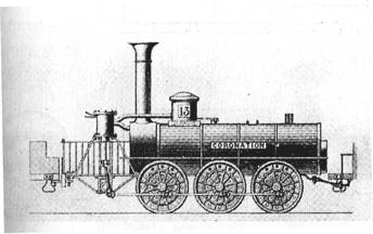
The Coronation
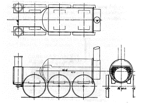
General
Arrangement of the Wilberforce Class Locomotives
This class of engines were in extensive use on the Stockton and Darlington line in 1832 & 1836. Designed by Timothy Hackworth, they were built by both Hawthorn and Stephenson. They had boilers 13 ft. long, 44"dia., the fire place was in a tube 29" dia. and 9 ft. long, the fire-door being at the same end as the stack. At the end of this tube farthest from the stack the flame was divided and the heat returned through a group of copper tubes on each side of the fire place. The smoke box received the products of combustion from both groups of tubes and communicated with the stack in the usual way. There were 53 tubes on each side of the fire tube, their length being 4 feet and outside diameter 1_". The arrangement of smoke box is shown in detail. These engines required a tender for coal at one end and one for water at the other.
The following descriptions are from Young’s Timothy Hackworth and the Locomotive:
While
the Globe was still
under construction, Hackworth was called on to design a number of locomotives
for the coal traffic, which was greatly increasing on the railway, and for
which the existing engine power was wholly inadequate. Accordingly plans were
prepared for two types of engines, six of each being built, not greatly
differing in design, except with regard to the boilers, with inside frames, and
all placed on six coupled wheels, 4 ft. diameter, and spring mounted
throughout. In these engines Hackworth followed the arrangement of inverted
cylinders devised by him in the Royal George. The original features of the first six
consisted in the power being communicated from the cylinders to a crank shaft,
in fixed bearings, and thence to the driving wheels through coupling rods. Two
feed pumps were, for the first time, fitted to each engine, and one class had
what is termed a straight multi-tubular boiler," consisting of a tube or
flue 9 ft. long, 2 ft. 6 ins. diameter, with one end inserted in the fire grate
end of the boiler. The other end was separated from the boiler by a partition
plate, with a series of copper tubes, 4 ft. long, conveying the vapour through
the remaining portion of the boiler (which was 13 ft. long) to the smoke-box,
the latter being at the contrary end to the fire. The cylinders, 14-1/2 ins.
diameter by 16 ins. stroke, were placed vertically in front of the smoke-box;
their connecting rods working down to a crank shaft, in fixed bearings -
without wheels - directly beneath. Two cranks were keyed on to the end of the
shaft at right angles, and from these cranks coupling rods connected the power
to the whole set of six wheels. The slide valves - which had a considerable
amount of "lap" for working expansively - were actuated by two eccentrics,
and made to reverse by a single lever. The two force pumps were worked by the
same eccentrics.
These
engines were called long engines," and were also known as the Majestic type to distinguish them from the second
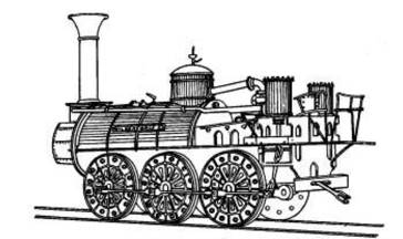
or Wilberforce type. In the latter the chief
difference was in the heating surface of the boiler, termed a "return
multi-tubular fire-tube," the valve gear, cylinders, wheels and
connections were similar to the former, except that the force pumps were worked
by separate eccentrics, and the cylinders were mounted oil framing projecting 6
ft. past the spherical end of the boiler. The boiler was 10 ft. long, 4 ft. 4
iris. diameter, with one flat and one spherical end. The heating surface
consisted of a tapered fire-tube, 8 ft. long, 2 ft. 4 ins. diameter at the
larger end - which was inserted in the flat end of the boiler, and contained
the fire-grate s- and 2 ft. in diameter at the smaller end, which was inserted
in a D-shaped box. The heated vapour, passing from the fire through the main
flue into the D-shaped box, was returned through the series of copper tubes
surrounding the main flue on all sides except the bottom. The copper tubes were
8 ft. long, and were inserted in the D box and flat boiler end-plate, where a
semi-circular smoke-box half encompassing the mouth of the main flue, conveyed
the smoke into the chimney.
The
various details for the six Majestic engines were manufactured, one-half by R. & W. Hawthorn
and one-half by Robert Stephenson & Co. The names and numbers were Majestic No. 12; Coronation
No. 13; William the Fourth
No. 14; Northumbrian
No. 15; Lord Brougham
No. 17; and Shildon No.
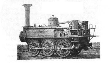
18. There does not appear to be any accurate drawing of the Majestic type of engine. Theodore West has given an
outline sketch of the Coronation
in his "Evolution of the Locomotive Engine," for which he says he was
indebted to an old Stockton & Darlington driver, William Craggs, who worked
the engine, and whose son made a sketch of it from which West's outline was
taken. There is a drawing also in the Science Museum, South Kensington, which,
however, is not an authoritative one, and while we give both sketches, which
show correctly the position of the cylinders in front of the chimney, we may
also add that John Hackworth referred to West's outline as a "grotesque
simile." He states also that the actual erection of the Coronation, as well as the five other locomotives
of this type, was carried out at New Shildon. The "Majestic" class
were all alike externally, but differed in the number and arrangement of the
boiler tubes. In one of Hackworth's account books in which the running expenses
of the different engines are entered for the year 1831, the Majestic is at
first called No. 2 Bedlington,
but under date August 2nd is a note saying "the Bedlington was this day christened the Majestic "
The
Wilberforce engines were Director
No. 16; Darlington
No. 19; Adelaide No.
20; Earl Grey No. 21; Lord Durham No. 22; and Wilberforce No. 23. Of the latter six, three were
built by Robert Stephenson & Co., Nos. 16, 20 and 22, and three by R. &
W. Hawthorn, Nos. 19, 21 and 23.