DIONYSIS LARDNER, THE STEAM ENGINE EXPLAINED AND ILLUSTRATED
with
Additions and notes by James Renwick, LL.D.
Philadelphia: Carey and Hart, 1836.
Ed. Downloaded
from the U. of Rochester Steam Collection (http://www.history.rochester.edu/steam/),
some corrections and additions made based on the original text. This excerpt
contains Chapters 13 & 14. JMcV.,
May 2008
CHAP.
XIII.
Steam Navigation.
FORM AND ARRANGEMENT OF MARINE ENGINES. -
EFFECTS OF SEA. WATER AND BOILERS. - REMEDIES FOR THEM. - BLOWING OUT.- IN-
DICTATORS OF SALTNESS.- SEAWARD'S INDICATOR.- HIS METHOD OF BLOWING OUT .-
FIELD'S BRINE PUMPS.- TUBULAR CONDENSER APPLIED BY MR. WATT.- HALL'S
CONDENSORS.- COPPER BOILERS.- PROCESS OF STOKING.- MARINE BOILERS.- MEANS OF
ECONOMISING FUEL.- COATING MARINE BOILERS OF FELT.- NUMBER ONE ARRANGEMENT OF
FURNACES AND FLUES.- HOWARD'S ENGINE.- RECENT IMPROVEMENTS MESSRS.- MAUDSLAY
AND FIELD.- HUMPHRY'S ENGINE.- COMMON PADDLE - WHEEL. - FEATHERING PADDLES.-
MORGAN'S WHEELS.- THE SPLIT PADDLE.- PROPORTION OF POWER TO TONNAGE.- IMPROVED
EFFICIENCY OF MARINE ENGINES.- IRON STEAM- VESSELS.- STEAM-NAVIGATION TO INDIA.
Among the many ways in which the steam-engine
has ministered to the advancement of civilisation and social progress of the
human race, there is none more important or more interesting than its
application to navigation. Before it lent its giant powers to the propulsion of
steam locomotion over the waters of the deep was attended with so much danger
and uncertainty that, as a common proverb, it became the type and the
representative of every thing which was precarious and perilous. The
application, however, of steam to navigation has rescued the mariner and the
voyager from many of the dangers of wind and water; and even in its present
state, putting out of view its probable improvement, it has rendered all
voyages of moderate length as safe, and very nearly as regular, as journeys overland.
As a means of transport by sea, the application of this power may be considered
as established; and it is now receiving improvements by which its extension to
the longest class of ocean voyages is a question not of practicability, but
merely of profit.
The manner in which the steam-engine is
rendered an instrument for the propulsion of vessels must in its general
features be so familiar to every one as to require but short explanation. A
shaft is carried across the vessel, being continued on either side beyond the
timbers: to the extremities of this shaft, on the outside of the vessel, are
fixed a pair of wheels constructed like undershot waterwheels, having attached
to their rims a number of flat boards called paddle-boards. As the wheels
revolve, these paddle-boards strike the water, driving it in a direction
contrary to that in which it is intended the vessel should be propelled. The
moving force imparted to the water thus driven backwards is necessarily
accompanied by a reaction upon the vessel through the medium of the
paddle-shaft, by which the vessel is propelled forwards. On the paddle-shaft
two cranks are constructed, similar to the cranks already described on the axle
of the driving wheels of a locomotive engine. 'These cranks are placed at right
angles to each other, so that when either is in its highest or lowest position
the other shall be horizontal. They are driven by two steam-engines, Which are
placed in the hull of the vessel below the paddle-shaft. In the earlier
steamboats a single steam-engine was used, and in that case the unequal action
of the engine on the crank was equalised by a flywheel. This, however, has been
long since abandoned In European
vessels, and the use of two engines is now almost universal. By the relative
position of the cranks it will be seen, that when either crank is at its dead
points, the other will be in the positions most favourable to its action, and
in all intermediate positions the relative efficiency of the cranks will be
such as to render their combined action very nearly uniform. The steam-engines
used to impel vessels may be either condensing engines, similar to those of
Watt, and such as are used in manufactures generally, or they may be non
condensing and high-pressure engines, similar in principle to those used on
railways. Low-pressure condensing engines are, however, universally used for
marine purposes in Europe and to some extent in the United States. In the
latter country, however, high-pressure engines are also in pretty general use,
on rivers where lightness is a matter of importance The arrangement of the
parts of a marine engine differs in some respects from that of a land engine.
The limitation of space, which is unavoidable in a vessel, renders greater
compactness necessary. The paddle-shaft on which the cranks to be driven by the
engine are constructed being very little below the deck of the vessel, the beam
and connecting rod could not be placed in the position in which they usually
are in land engines, without carrying the machinery to a considerable elevation
above the deck. This is done in the steamboat engines used on the American
rivers; but it would be inadmissible in steamboats in general, and more
especially in seagoing steamers. The connecting rods, therefore, instead of
being presented downwards towards the cranks which they drive, must, in
steam-vessels, be presented upwards, in the impelling force received from
below. If, under these circumstances, the beam were in the usual position above
the cylinder and piston-rod, it. must necessarily be placed between the engine
and the paddle-shaft. This would require a depth for the machinery which would
be incompatible with the magnitude of the vessel. The beam, therefore, of
marine engines, instead of being above the cylinder and piston, is placed below
them. To the top of the
piston-rods cross pieces are attached of greater length than the
diameter of the cylinders, so that their extremities shall project beyond the
cylinders. To the ends of these cross pieces are attached by joints the rods of
a parallel motion : these rods are carried downwards, and are connected with
the ends of two beams below the cylinder, and placed on either side of it. The
opposite ends of these beams are connected by another cross piece, to which is
attached a connecting rod, which is continued upwards to the crank-pin, to
which it is attached, and which it drives. Thus the beams parallel motion, and
connecting rod of a marine engine, is similar to that of a land engine, only
that it is turned upside down; and in consequence of the impossibility of
placing the beam directly over the piston-rod, two beams and two systems of
parallel motion are provided, one on each side of the engine, acted upon by,
and acting on the piston-rod and crank by cross pieces. The proportion of the
cylinders differs from that usually observed in land engines, for like reasons.
The length of the cylinder of land engines is generally greater than its
diameter, in the proportion of about two to one. The cylinders of marine
engines are, however, commonly constructed with a diameter very little less
than their length. In proportion, therefore, to their power their stroke is
shorter, which infers a corresponding shortness of crank and a greater
limitation of play of all the moving parts in the vertical direction. The
valves and the gearing by which they are worked, the air-pump, the condenser,
and other parts of the marine engines, do not materially differ from those
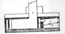
already described in land engines. These arrangements of a marine engine will be
more clearly understood by reference to fig. 119. in which is represented a
longitudinal section of a marine engine with its boiler as placed in a
steam-vessel. The sleepers of oak, supporting the engine, are represented at x,
the base of the engine being secured to these by bolts passing through them
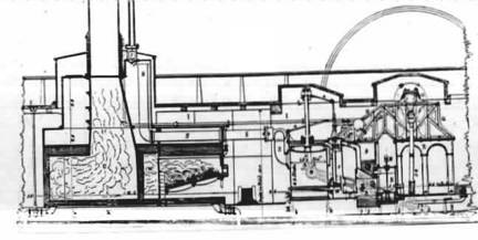
Fig.
119
and the bottom timbers of the vessel; s is
the steam-pipe leading from the steam-chest in the boiler to the slides c, by
which it Is admitted to the top and bottom of the cycle The condenser is represented
at B, and the air-pump at E. The hot well is seen at F, from which the feed is
taken for the boiler; L is the piston-rod connected by the parallel motion a
with the beam H, working on a centre K, near the L base of the engine. The
other end of the beam I drives the connecting rod m, which extends upwards to
the crank it works upon the paddle-shaft Q. R is the framing by which the
engine is supported. The beam here exhibited is shown on dotted lines as being
on the further side of the engine. A similar beam similarly placed, and moving
on the same axis, must be understood to be at this side connected with the
cross head of the piston in a like manner by a prior motion, and with a cross
piece attached to the lower end of the connecting rod and to the opposite hewn.
The eccentric which works the slides is placed upon the paddle L and the
connecting arm which drives the slides may be easily detached when the engine
requires to be stopped. Sections of the boiler, grate, and flues is represented
at w-u. The safety-valve y is enclosed beneath a pipe carried beside the
chimney and is inaccessible to the engine. They are the cocks responsible for
blowing the salted water from the boiler and I-I the feed-pipe. The general
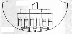
arrangement of the engine-room of a steam vessel is represented in fig 120. The
nature of the effect required to be produced by steam engines does not render
either necessary or possible. One great regularity of action which is
indispensable in a steam engine is applied to the pipes of manufacture. The
eccentric of the surface of the sea wall causes the immersion of the
paddle-wheels to be subject to great variation, and the resistance produced by
the water to the engine will undergo a corresponding change. The governor,
therefore, and other parts of the apparatus, contrived for giving to the engine
that great regularity required in manufactures, are omitted in nautical
engines, and nothing is introduced save what is necessary to maintain the
machine in its full working efficiency.
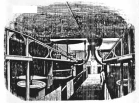
Fig.
120
To save space, marine boilers are constructed
so as to produce the necessary quantity of steam within the smallest possible
dimensions.
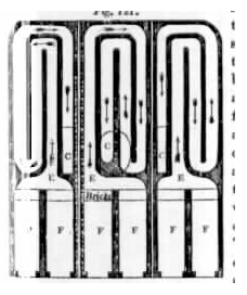
Fig.
121
With this view a more extensive surface in
proportion to the capacity of the boiler is exposed to the action of the fire.
The flues, by which the flame and heated air are conducted to the chimney, are
so constructed that the heat may act upon the water on every side in thin
oblong shells or plates. This is accomplished by constructing the flues so as
to traverse the boiler backwards and forwards several times before they
terminate in the chimney. Such an
arrangement renders the expense of the boilers greater, but their steam
producing power is proportionally augmented, and experiments made by Mr. Watt,
at Birmingham, have proved that such boilers with the same consumption of fuel
will produce, as compared with common land boilers, an increased evaporation in
the proportion of about three to two. M
The form and arrangement of the water-spaces
and flues in marine boilers may be collected from the sections of the boilers
used in some of the government steamers, exhibited fig. 121, 122, 123. A
section made by a horizontal plane passing through the flues is exhibited in
fig. 121. The furnaces F communicates in pairs with the flues E the air
following the course through the flues represented by the arrows. The flue E
passes to the back of the boiler, then returns to the front, then to the back
again, and is finally carried back to the front, where it communicates at c
with the curved flues represented in the transverse vertical section, 122. This
curved flue B finally terminates in the chimney A. There are in this case three
independent boilers, each worked by two furnaces communicating with the same
system of flues; and in the curved flues B fig. 1 22., by which the air is finally
conducted through the chimney, are placed three independent dampers, by means
of which the furnace of each boiler can be regulated independently of the
other, and by which each boiler may be separately detached from communication
with the chimney The letters of reference in the horizontal section, fig. 121,
correspond with those in the transverse vertical section, fig 122., with E
representing the commencement of the flues, and C their termination. A
longitudinal section of the boiler made by a vertical plane extending from the
front to the back is given in fig 123,
where f, as before, is the furnace, g the grate-bars sloping downwards
from the front to the back, h the fire-bridge, c the commencement of the flues,
and A the chimney. An elevation of the front of the boiler is represented in
fig. 124., showing two of the fire-doors closed, and the other two removed,
displaying the position of the grate-bars in front. Small openings are also
provided, closed by proper doors, by which access can be had to the under side
of the flues between the foundation timbers of the engine for the purpose of
cleaning them. Each of these boilers can be worked independently of the others.
By these means, when at sea, the engine may be worked by any two of the three
boilers, while the third is being cleaned and put in order. In all seagoing
steamers, multiple boilers are present providing for this purpose.. In the
boilers are represented the flues all upon the same level, winding backwards
and forwards without passing one above the other. In the other boilers,
however, the flues, after passing backwards and forwards near the bottom of the
boiler, turn upwards and pass backwards and forwards through a level of the
water nearer its surface, finally terminating in the chimney. More heating
surface is thus obtained with the same capacity of boiler. The most formidable
difficulty which has been encountered in the application of the steam-engine to
sea voyages, has arisen from the necessity of supplying the boiler with sea
water instead of pure fresh water. The sea-water is injected into the condenser
for the purpose of condensing the steam, and it is thence, mixed with the
condensed steam, to be conducted as feeding water into the boiler.
Fig
123
Fig.
124
Sea-water holds, as is well known, certain alkaline
substances in solution, the principal of which is muriate of soda, or common
salt. Ten thousand grains of pure ;sea water contain two hundred and twenty
grains of common salt, remaining ingredients being thirty-three grains of
sulphate of soda, forty-two grains of muriate of magnesia, and eight grains of
muriate of lime. The heat which converts pure water into steam does not at the
same time evaporate those salts which the water holds in solution. As a
consequence, it follows, that as evaporation in the boiler is continued, the
salt, which was held in solution by the water which been evaporated, remains in
the boiler, and enters into solution with the water remaining in it. The
quantity of salt contained in sea-water being considerably less than that which
water is capable of holding in solution, the process of evaporation for some
time is attended with no other effect than to render the water in the boiler a
stronger solution of salt. If, however, this process be continued, the quantity
of salt retained in the boiler having constantly an increasing proportion to
the quantity of Water, it must at length render the water in the boiler a
saturated solution-that is, a solution containing as much salt as at the actual
temperature it is capable of holding in solution. If, therefore, the
evaporation be continued beyond this point, the salt disengaged from the water
evaporated instead of entering into solution with the water remaining in the
boiler will be precipitated in the form of sediment; and if the process be
continued in the same manner, the boiler would at length become a mere
salt-pan. But besides the deposition of salt sediment in a loose form, some of
the constituents of sea-water having an attraction for the iron of the boiler,
correct upon it in a scale or crust in the same manner as earthy matters held
in solution by spring-water are observed to form and become incrusted on the
inner surface of land-boilers and of common culinary vessels. The coating of
the inner surface of a boiler by incrustation and the collection of salt
sediment in its lower parts, are attended with effects highly injurious to the
materials of the boiler. The crust and segment thus formed within the boiler
are almost nonconductors of heat, and placed, as they are, between the water
contained in the boiler and the metallic plates which form it, they obstruct
the passage of heat from the outer surface of the plates in contact with the
fire to the water. The heat, therefore, accumulating iii the boilerplates so as
to give them a much higher temperature than the water within the boiler, has
the effect of softening them, and by the unequal temperature which will thus he
imparted to the lower plates which are incrusted, compared with the higher
parts which may not he so, an unequal expansion is produced, by which the
joints and seams of the boiler are loosened and opened, and leaks produced.
These injurious effects can only he prevented by either of two methods; first,
by so regulating the feed of the boiler that the water it contains shall not be
suffered 'to reach the point of saturation, but shall be so limited in its
degree of saltness that no injurious incrustation or deposit shall be formed; secondly,
by the adoption of some method by which the boiler may be worked with fresh
water.' This end can only be attained by condensing the steam by a jet of fresh
water, and working the boiler continually by the fresh water, since a supply of
fresh water sufficient for a boiler worked in the ordinary way could never be
commanded at sea.
The method by which the saltiness, of the
water in the boiler is most commonly prevented from exceeding a certain limit
has been to discharge from the boiler into the sea a certain quantity of
over-salted water, and to supply its place introduced into the condenser
through the injection-cock for the purpose of condensing the steam, this water
being mixed with the steam so condensed, and being, weaker solution of salt
than common sea-water. therefore, a To effect this, cocks called blow-off
cocks, are usually placed in the lower parts of the boiler, where the
over-salted, and therefore heavier, parts of the water collect. The pressure of
the steam and incumbent weight of the water in the boiler force the lower
strata of water out through these cocks; and this process, called blowing out,
is, or ought to be, practised at such intervals as will prevent the water from
becoming has been blown out in over salted. When the salted water has been
blown out in this manner, the level of the water in the boiler is restored by a
feed of corresponding quantity. This process of blowing out, on the due and
regular observance of which the preservation and efficiency of the boiler
mainly depend, is too often left at the discretion of the engineer, who is, in
most cases, not even supplied with the proper means of ascertaining the extent
to which the process should be carried. It is commonly required that the
engineer should blow out a certain portion of the water in the boiler every two
hours, restoring the level by a feed of equivalent amount; but it is evident
that the sufficiency of the process founded on such a rule must mainly depend
on the supposition that the evaporation proceeds always at the same rate, which
is far from being the case with marine boilers. An indicator, by which the
saltness of the water in the boiler would always be exhibited, ought to be
provided, and the process of blowing out should be regulated by the
inclinations of that instrument. To blow out more frequently than is necessary
is attended with a waste of fuel ; for hot water is thus discharged into the
sea while cold water is introduced in its place, and consequently all the heat
necessary to produce the difference of the temperatures of the water blown out
and the feed introduced is lost. If, on the other hand, the process of blowing
out be observed less frequently than is necessary, then more or less
incrustation and deposit may be produced, and the injurious effects already
described ensue As the specific gravity of water holding salt in solution is
increased with every increase of the strength of the solution, any form of
hydrometer capable of exhibiting a visible indication of the specific gravity
of the water contained in the boiler would serve the purpose of an indicator,
to show the process of blowing out is necessary, and when it has been carried
to a sufficient extent. The application of such instruments, however, would be
attended with some practical difficulties in the case of sea-boilers. The
temperature at which a solution of salt boils under a given pressure varies
considerably with the strength of the solution ; the more concentrated the
solution is, the higher will be its boiling temperature under the same
pressure. A comparison, therefore, of a steam-gauge attached to the boiler, and
a thermometer immersed in it, showing the pressure and the temperature, would
always indicate the saltness of the water; and it would not be difficult so to
graduate these instruments as to make them at once show the degree of saltness.
If the application of the thermometer he
considered to be attended with practical difficulty, the difference of
pressures under which the salt water of the boiler and fresh water of the same
temperature boil, might be taken as an indication of the saltness of the water
in the boiler, and it would not be difficult to construct upon this principle a
self-registering instrument, which would not only indicate but record from hour
to hour the degree of saltness of the water. A small vessel of distilled water
being immersed in the water of the boiler would always have the temperature of
that water, and the steam produced from it communicating with a steam-gauge,
the pressure of such steam would be indicated by that gauge, while the pressure
of the steam in the boiler under which pressure the salted water boils might be
indicated by another gauge. The difference of the pressures indicated by the
two gauges would thus become a test by which the saltness of the water in the
boiler would be measured. The two pressures might be made to act on opposite
ends of the same column of mercury contained in a siphon tube, and the
difference of the levels of the two surfaces of the mercury would thus become a
measure of the saltness of the water in the boiler. A self registering
instrument founded on this principle formed part of the self-registering
team-log which I proposed to introduce into steam-vessels some time since. (21
1.) The Messrs. Seaward of Limehouse have adopted, in some of their recently
constructed engines, a method of indicating the saltness of the water, and of
measuring the quantity of salted water or brine discharged, by blowing out. A
glass gauge, similar in form to that already described in land engines (156.),
is provided to indicate the position of the surface of the water in the boiler.
In this gauge two hydrometer balls are provided, the weight of which in
proportion to their magnitude is such that they would both sink to the bottom
in a solution of salt of the same strength as common sea-water. When the
quantity of salt exceeds 5/52 parts of the whole weight of the water, the
lighter of the two balls Will float to the top; and when the strength is
further increased until the proportion of salt exceeds, 6/52 parts of the
whole, then the heavier ball will float to the top. The actual quantity of salt
held in solution by sea-water in its ordinary state is ', part of its whole
weight; and when by evaporation the proportion of salt in solution has become
9/52 parts of the whole, then a deposition of salt commences. With an indicator
such as that above described, the ascent of the lighter hydrometer ball gives
notice of the necessity for blowing out, and the ascent of the heavier may be
considered as indicating the approach of an injurious state of saltness in the
boiler. The ordinary method of blowing out the salted water from a boiler is by
a pipe having a cock in 'it leading from the boiler through the bottom of the
ship, or at a point low down at its side. Whenever the engineer considers that
the water in the boiler has become so salted that the process of blowing out
should commence, he opens the cock communicating by this pipe with the sea, and
suffers an indefinite and uncertain quantity of water to escape. In this way he
discharges, according to the magnitude of the boiler, from two to six tons of
water, and repeats this at intervals of from two to four hours, as he may
consider to be sufficient. If, by observing this process, he prevents the boiler
from getting incrusted during the voyage, he considers his duty to be
effectually discharged, forgetting that he may have blown out many times more
water than is necessary for the preservation of the boiler, and thereby
produced a corresponding and unnecessary waste of fuel. In order to limit the
quantity of water discharged, Messrs. Seaward have adopted the following
method. In fig. 125. is represented a transverse section of a part of a
steam-vessel; w is the waterline of the boiler, B is the mouth of a blow-off
pipe, placed near the bottom of the boiler. This pipe rises to A, and turning
in the horizontal direction, A c is conducted to a tank T, which contains
exactly a ton of water. This pipe communicates with the tank by a cock D,
governed by a lever it. When this lever is moved to DI, the cock D is Open, and
when it in moved to K, the cock D is closed. From the same tank there proceeds
another pipe F, which issues from the side of the vessel into the sea governed
by a cock v, which is likewise put in connection with the lever H, so that it
shall be opened when the lever H is drawn to the Position F', the cock D` being
closed in all positions of the lever between x and V. Thus, whenever the cock F
communicating with the sea is open, the cock D` communicating with the boiler
is closed, and vice versa, 'both cocks being closed when the lever is in the
intermediate position K. By this arrangement the boiler cannot, by any neglect
in blowing off, be left in communication with the sea, nor can more than a ton
of water be discharged except by the immediate act of the engineer. The
injurious consequences are thus prevented which sometimes ensue when the
blow-off cocks are left open by any neglect on the part of the engineer. When
it is necessary to blow off, the engineer moves the lever H, to the position
D". The pressure of the steam in the boiler on the surface of the water w
forces the salted water or brine up the pipe B A, and through the open cock c
into the tank, and this continues until the tank is filled: when that takes
place, the lever is moved from the position D' to tile position P', by which
the cock D is closed, and the cock F opened. The water in the tank flows
through the pipe E into the sea, air being admitted through the valve Y, placed
at the top of the tank, opening inwards. A second ton of brine is discharged by
moving the lever back to the position V, and subsequently returning it to the
position F; and in this way the brine is discharged ton by ton, until the
supply of water from the feed which replaces it has caused both the balls in
tile indicator to sink to the bottom (212)
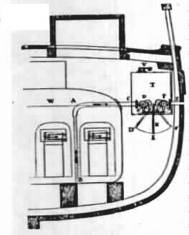
Fig.
125
A different method of preserving the
requisite freshness of the water in the boiler has been adopted by Messrs.
Maudslay and Field, and introduced with success into the Great Western and
other steam-vessels. Pumps called brine-pumps are put into communication with
the lower part of the boiler, and so constructed as to draw the brine
therefrom, and drive it into the sea. These brine-pumps are worked by the engine,
and their operation is constant. The feed-pumps are likewise worked by the
engine, and they bear such a proportion to the brine-pumps that tile quantity
of salt discharged in a given time in the brine is equal to the quantity of
salt introduced in solution by the water of the feed-pumps. By this means the
same actual quantity of salt is constantly maintained in the boiler, and
consequently the strength of the solution remains invariable. If the brine
discharged by the brine-pumps contains 5/32 parts of salt while the water
introduced by the feed-pumps contains only 1/32 part, then it is evident that
five cubic feet of the feeding water will contain no more salt than is
contained in one cubic foot of brine. Under such circumstances the brine-pumps
would be so constructed as to discharge 1/5 of the water introduced by the
feed-pumps, so that 4/5 of all the water introduced into the boiler would be
evaporated, and rendered available for working the engine. To save the heat of
the brine, a method has been adopted in the marine engines constructed by
Messrs. Maudslay and Field similar to one which has been long practised in
steam boilers, and in various apparatus for the warming of buildings. The
current of heated brine is conducted from the boiler through a tube which is
contained in another, through which the feed is introduced. The warm current of
brine, therefore, as it passes out, imparts a considerable portion of its heat
to the cold feed which comes in ; and it is found that by this expedient the
brine discharged into the sea may be reduced to a temperature of about 100'.
This expedient is so effectual that when the apparatus is properly constructed,
and kept in a state of efficiency, it may be regarded as nearly a perfect
preventive against the incrustation, and the deposition of salt in the boilers,
and is not attended with any considerable waste of fuel. (213) About the year
1776, Mr. Watt invented a tubular condenser, with a view to condense the steam
drawn off from the cylinder without the process of injection. This apparatus
consisted of a number of small tubes connecting the top and bottom of the
condenser, arranged in a manner not very different from that of the tubes which
traverse the boiler of a locomotive engine. These tubes were continually surrounded
by cold water, and the steam, as it escaped from the cylinder passing through
them, was condensed by their cold surfaces, and collected in the form of water
in a reservoir below, from whence it was drawn off by a pump in the same manner
in engines which condensed by injection. One of the advantages proposed by this
expedient was, that no atmospheric air would be introduced into the condenser,
as is always the case when condensation by injection is practised. Cold Water
which is injected, has always combined with it more or I common air. When this
water is mixed with the condensed steam, the elevation of its temperature
disengages the air combined with it, and this air circulating to the cylinder
vitiates the vacuum. One of the purposes for which air-pump in condensing
steam-engines was provided, a from which it took its name, was to draw off this
air. If, however, a tubular condenser could be made to act v the necessary
efficiency, no injection water would be introduced for condensation, and the
pump would have no other duty except to remove the small quantity of water
produced by the condensed steam. That water being subsequently carried back to
the boiler by the feed-pumps, a constant system of circulation would be
maintained, and the boiler would never require any fresh supply of water,
except what might be necessary to make good the waste by leakage a other
causes. This contrivance has been of late years revived by Samuel Hall of
Basford, near Nottingham, with a view,, supersede in marine engines the
necessity of using sea-water in the boilers. Mr. Hall proposes to make marine
boiler with fresh water to condense the steam without injection a tubulated
condenser, and to provide by the distillation of sea-water the small quantity
of fresh water which would -necessary to make good the waste. These condensers
have been introduced into several steam-vessels: in some they have been
continued, and in others abandoned, and various opinions are entertained of
their efficacy. I have not been able to obtain the results of any satisfactory
experiments them, and cannot therefore form a judgment of their usefulness. Mr.
Watt abandoned these condensers from find ii that the condensation of the steam
was not sufficient sudden, and that consequently at the commencement of the
stroke the piston was subject to a resistance which injuriously diminished the
amount of the moving power, whereas condensation by jet was almost
instantaneous, and the efficiency of the piston throughout the entire stroke
was more uniform. Mr. Watt also found that a fur collected around the tubes of
the condenser, so as to obstruct the free passage of heat from the steam to the
water of the cold cistern; and that, consequently, the efficiency of the
condenser was gradually impaired and could only be restored by frequent
cleansing. It is stated by Mr. Hall that a vacuum is preserved in his
condensers as perfect as that which is maintained in the ordinary condensers by
injection. It is objected, on the other hand, that without the injection water
and the air which accompanies it being introduced into his condensers, Mr. Hall
uses as large and powerful an air-pump as those which are used in engines of
equal power condensing by injection; that, consequently, the vacuum which is
maintained is produced, not as it ought to be altogether by the condensation of
steam, but by the air-pump drawing off the uncondensed steam. To whatever
extent this may be true, the efficacy of the machine, as indicated by the
barometer-gauge, is only apparent; since as much power is necessary to pump
away any portion of uncondensed vapour as is obtained by the vacuum produced by
the absence of that vapour. A tubular condenser of the form proposed by Mr.
Hall is represented in fig. 126.; a is the upper part of the condenser to which
steam is admitted from the slide after having worked the piston; k is the
section of a thin plate, forming the top of - the condenser, perforated with
small holes, in which the tubes are inserted so as to be steam-tight and
watertight.
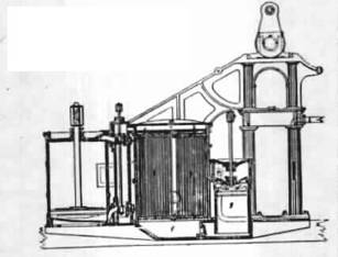
Fig.
126
Water is admitted to flow around these tubes
between the top k and the bottom d of the condenser, so as to keep them
constantly at a low temperature. The steam passes from a through the tubes to
the lower chamber f of the condenser, where it is reduced to water by the cold
to which it has been exposed. A supply of cold water is constantly pumped
through the condenser, so as to keep the tubes at a low temperature. The
air-pump g is of the usual construction, having valves in the piston opening
upwards, and similar valves in the cover of the pump Also opening upwards. The
water formed by the condensed steam in f is drawn through the foot-valve, and
after passing through the piston valves, is discharged by the upstroke of the
piston into the hot well. Any air, or other permanent gas, which may be
admitted by leakage through the tubes of the condenser, or by any other means,
is likewise drawn out by this pump, and when drawn into the hot well is carried
from thence to the feeding apparatus of the boiler, to which it is transferred
by the feed-pump. A provision is likewise made by which the steam escaping at
the safety-valve is condensed and carried away to the feeding cistern. (214.)
One of the remedies proposed for the evil consequences arising from incrustation
is the substitution of copper for iron boilers. The attraction which produces
the adhesion of the calcareous matter held in solution by salt water to the
surface of iron has no existence in copper, and all the saline and other
alkaline matter precipitated in the boiling water in copper boilers is
suspended in a loose form, and carried off by the process of blowing out.
Besides the injury arising from the deposition of salt and the incrustation on
the inner surface of boilers, an evil of a formidable kind attends the
accumulation of soot mixed with salt in the flues, which proceeds from the
leaks. In the seams of the boiler there are numerous apertures, of dimensions
so shall as to be incapable of being rendered stanch by any practicable means,
through which the water within the boiler filters, and the salt which it
carries with it mixes with the soot, forming a compound which rapidly corrodes
the boilers. This process of corrosion in the flues takes place not less in
copper than in iron-boilers. In cleansing the flues of a copper boiler, the
salt and soot which was thrown out upon the iron-plates which formed the
flooring of the engine-room, having remained there for some time, left behind
it a permanent appearance of copper on the iron flooring, arising from the
precipitation of the copper which bad combined with the soot and salt in the
flues.* In this case the leaks from whence the salt proceeded were found, on
careful examination, so unimportant, that the usual means to stanch them could
not be resorted to without the risk of increasing the evil. (215.) In the
application of the steam-engine to the propulsion of vessels in voyages of
great extent, the economy of fuel acquires an importance greater than that
which appertains to it in land-engines, even in localities the most removed
from coal mines, and where its expense is greatest. The practical limit to
steam-voyages being determined by the greatest quantity of coals which a
steam-vessel can carry, every expedient by which the efficiency of the fuel can
be increased becomes a means, not merely of a saving of expense, but of ark
increased extension of steam-power to navigation. Much attention has been
bestowed on the augmentation of the duty of engines in the mining districts of
Cornwall, where the question of their efficiency is merely a question of
economy, but far greater care should be given to this subject when the
practicability of maintaining intercourse by steam between distant points of
the globe Will perhaps depend on the effect produced by a given quantity of
fuel. So long as steam-navigation was confined to river and channel transport,
and to coasting voyages, the speed of the vessel was a paramount consideration,
at whatever expenditure of fuel it might be obtained; but since
steam-navigation has been extended to ocean-voyages, where coals must be
transported sufficient to keep the 'engine in operation for a long period of
time without a fresh relay, greater attention has been bestowed upon the means
of economising it. Much of the efficiency of fuel must depend on the management
of the fires, and therefore on the skill and care of the stokers. Formerly the
efficiency of firemen was determined by the abundant production of steam, and
so long as the steam was evolved in superabundance, however it might have blown
off to waste, the duty of the stoker was considered as well performed. The
regulation of the fires according to the demands of the engine were not thought
of, or whether much or little steam was wanted, the duty of the stoker was to
urge the fires to their extreme limit. Since the resistance opposed by the
action of the paddle wheels of a steam-vessel varies with the state of the
weather, the consumption of steam in the cylinders must undergo a corresponding
variation; and if the production of steam in the boilers be not proportioned to
this, the engines will either work with less efficiency than they might do
under the actual circumstances of the weather, or more steam will be produced
in the boilers than the cylinders can consume, and the surplus will be
discharged to waste through the safety-valves. The stokers of the marine
engine, therefore, to perform their duty with efficiency, and obtain from the
fuel the greatest possible effect, must discharge the functions of a
self-regulating furnace, such as has been already described: they must regulate
the force of the fires by the amount of steam which the cylinders are capable
of consuming, and they must take care that no unconsumed allowed to be carried
away from the ash-pit. (2 1 6.) Until within a few years of the present time
the heat radiated from every part of the surface of the boiler was allowed to
go to waste, and to produce injurious effects on those parts of the vessel to
which it was transmitted. This evil, however, has been lately removed by
coating the boilers, steam pipes , &c. of steam-vessels with felt, by which
the escape of heat from the surface of the boiler is very nearly, if not
altogether, prevented. This felt is attached to the boiler-surface y a thick
covering of white and red lead. This expedient was first applied in the year
1818 to a private steam-vessel of Mr. Watt called the Caledonia, and it was
subsequently tried later in another vessel, the machinery of which was
constructed at Soho, called the Tames Wait. The economy of fuel depends in a
considerable degree on the arrangement of the furnaces, and the method of
feeding them. In general each boiler is worked by two or more furnaces
communicating with the same system of flues. While the furnace is fed, the door
being open, a stream of cold air ashes in, passing over the burning fuel and
lowering the temperature of the flues: this is an evil to be avoided. But, on
the other hand, if the furnaces be fed at distant intervals, then each furnace
will be unduly heaped with fuel, a great quantity of smoke will be evolved, and
the combustion of the fuel will be proportionally imperfect. The process of
cocking in front of the grate, which would insure a complete combustion of the
fuel, has been already described (147.). A frequent supply of coals, however,
laid carefully on the front I art of the grate, and gradually pushed backwards
as each I fresh feed is introduced, would require the fire-door to be
frequently opened, and cold air to be Admitted. It would also require greater
vigilance on the part of the stokers than an generally be obtained in the
circumstances in which they fork. In steam-vessels the furnaces are therefore
fed less 'frequently, fuel introduced in greater quantities, and a less perfect
combustion produced. When several furnaces are constructed under the same
boiler, communicating with the same system of flues, the process of feeding,
and consequently opening one of them, Obstructs the due operation of the
others, for the current of cold air which is thus admitted into the flues
checks the draft and diminishes the efficiency of the furnaces in operation. It
was formerly the practice in vessels exceeding one hundred horsepower, to place
four furnaces under each boiler, communicating with the same system of flues.
Such an arrangement was found to be attended with a bad draft in the furnaces,
and therefore to require a greater quantity of heating surface to produce the
necessary evaporation. This entailed upon the machinery the occupation of more
space in the vessel in proportion to its power; it has therefore been more
recently the practice to give a separate system of flues to each pair of
furnaces, or, at most, to every three furnaces. When three furnaces communicate
with a common flue, two will always be in operation, while the third is being
cleared out; but if the same quantity of fire were divided among two furnaces,
then the clearing out of one would throw out of operation half the entire
quantity of fire, and during the process the evaporation would be injuriously
diminished. It is found by experience, that the side plates of furnaces are
liable to more rapid destruction than their roofs, owing, probably, to a
greater liability to deposit. Furnaces, therefore, should not be made narrower
than a certain limit. Great depth from front to back is also attended with
practical inconvenience, as it renders firing tools of considerable length, and
a corresponding extent of stoking room necessary. It is recommended, by those
who have had much practical experience in steam-vessels, that furnaces six feet
in depth from front to back should not be less than three feet in width, to
afford means of firing with as little injury to the side plates a in the
condition necessary as possible, and of keeping the fire tops of for the production
of the greatest effect. T the furnaces almost never decay, and seldom are
subject to an alteration of figure, unless the level of the water be allowed to
fall below. A form of marine engine was some years since processing much posed
and patented by Mr. Thomas Howard, possessing novelty temperature varying from
4000 to 500o. The surface exposed to the fire was computed at three fourths of
a square foot for each horsepower. The upper surface of the mercury was covered
by a very thin plate of iron in contact with it, and so contrived as to present
about four times as much Surface a& that exposed beneath the fire. Adjacent
to this a vessel of water was placed, maintained nearly at the boiling point,
and communicating by a nozzle and valve with the chamber immediately above the
mercury. At intervals corresponding to the motion of the piston a small
quantity of water was injected from this vessel, and thrown upon the plate of
iron resting upon the hot mercury. From this it received not only the heat
necessary to convert it into common steam, but to give it the qualities of
highly superheated steam. In fact, the steam thus produced had a temperature
considerably above that which corresponded to its pressure, and was, therefore,
capable of being deprived of more or less of its heat without being condensed.
(94.) The quantity of water injected into the steam-chamber was regulated by
the power at which the engine was intended to be worked. The fire was supplied
with air by a blower subject to exact regulation. The steam thus produced was
conducted to a chamber surrounding the working cylinder, and this chamber
itself was enclosed by another space through which the air from the furnace
passed before it reached the. flue. By this contrivance the air imparted its redundant
heat to the steam, a.% the latter passed to the cylinder, and raised its
temperature to about 4,NG, the pressure, however, not exceeding 25 lb. per
square inch. The valves, governing the admission of steam to the piston, were
adapted for expansive action.
The vacuum on the opposite side was
maintained by condensation in the following manner: - The condenser was a
copper vessel placed in a cistern of cold water, and the steam was admitted to
it from the cylinder by an eduction pipe in the usual way. A jet was introduced
from an adjacent vessel filled with distilled water, and the condensing water
and condensed steam were pumped from the condenser as in common engines. The
warm water thus pumped out of the R H and ingenuity, and having pretensions to a
very extraordinary economy of fuel, in addition to the advantages claimed by
Mr. Hall. In Mr. Howard's engines, the steam, as in Mr. Hall's, is constantly
reproduced from the same water, so that pure or distilled water may be used;
but Mr. Howard dispenses altogether with the use of a boiler. A quantity of
mercury is placed in a shallow wrought-iron vessel over a coke fire, by which
it is maintained at a temperature varying from 400 to 500. The surface exposed
to the fire was computed at three fourths of a square foot for each horsepower.
The upper surface of the mercury was covered by a very thin plate of iron in
contact with it, and so contrived as to present about four times as much
Surface a& that exposed beneath the fire. Adjacent to this a vessel of water
was placed, maintained nearly at the boiling point, and communicating by a
nozzle and valve with the chamber immediately above the mercury. At intervals
corresponding to the motion of the piston a small quantity of water was
injected from this vessel, and thrown upon the plate of iron resting upon the
hot mercury. From this it received not only the heat necessary to convert it
into common steam, but to give it the qualities of highly superheated steam. In
fact, the steam thus produced had a temperature considerably above that which
corresponded to its pressure, and was, therefore, capable of being deprived of
more or less of its heat without being condensed. (94.) The quantity of water
injected into the steam-chamber was regulated by the power at which the engine
was intended to be worked. The fire was supplied with air by a blower subject
to exact regulation. The steam thus produced was conducted to a chamber
surrounding the working cylinder, and this chamber itself was enclosed by
another space through which the air from the furnace passed before it reached
the. flue. By this contrivance the air imparted its redundant heat to the
steam, a.% the latter passed to the cylinder, and raised its temperature to
about 4,NG, the pressure, however, not exceeding 25 lbs. per square inch. The
valves, governing the admission of steam to the piston, were adapted for
expansive action.
The vacuum on the opposite side was
maintained by condensation in the following manner: - The condenser was a
copper vessel placed in a cistern of cold water, and the steam was admitted to
it from the cylinder by an eduction pipe in the usual way. A jet was introduced
from an adjacent vessel filled with distilled water, and the condensing water
and condensed steam were pumped from the condenser as in common engines. The
warm water thus pumped out of the condenser was drawn through 9. copper
worm" carried with many coils through a cistern of cold water, so that
when it arrived at the end of this pipe it was reduced nearly to the temperature
of the atmosphere. The pipe was thus brought to the vessel of distilled water
already mentioned, and the water supplied by it replaced. The water admitted to
the condenser through the condensing jet being purged of air, a small air-pump
was sufficient, since it had only to exhaust the condenser and tubes at
starting, and to remove the air which might be admitted by leakage. Mr. Howard
stated that the condensation took place as rapidly and perfectly as in the best
engines of the common kind.
An engine of this construction was in the
spring of 1835 Placed in the government steamer called the Comet. It was
stated, that though the machinery was not advantageously constructed, a part of
the engine being old, and not made especially for a boiler of this kind, the
vessel performed a voyage from Falmouth to Lisbon, in which the consumption of
fuel did not exceed a third of her former consumption when worked by Boulton
and Watt's engines, the former consumption of coals being about eight hundred
pounds per hour, and the consumption of Mr. Howard's engine being less than two
hundred and fifty pounds of coke per hour.
The advantages claimed for this contrivance
were the following: first, the small space and weight occupied by the
machinery-, arising from the absence of a boiler; second, the diminished
consumption of fuel; third, the reduced size of the flues; fourth, the removal
of the injurious effects arising from deposit and incrustation; fifth, the
absence of smoke. (218.) The method by which the greatest quantity of practical
effect can be obtained from a given quantity of fuel, must, however, mainly
depend on the extended application of the expensive principle. This has been
the means by which an extraordinary amount of duty has been obtained from the
Cornish engines. The difficulty of the application of this principle in marine
engines has arisen from the objections entertained in Europe to the use of
steam of high pressure under the circumstances in which the engine must be
worked at sea. To apply the expansive principle, it is necessary that the
moving power at t of the stroke shall considerably exceed the resistance, its
force being gradually attenuated till the completion of the stroke, when it
will at length become less than the resistance. This condition may, however, be
attained with steam of limited pressure, if the engine be constructed with a
sufficient quantity of piston-surface. This method of rendering the expansive
principle available at sea, and compatible with low-pressure steam, has
recently been brought into operation by Messrs. Maudslay and Field. Their
improvement consists in adapting two steam-cylinders in one engine, in such a
manner that the steam shall act simultaneously on both pistons, causing them to
ascend and descend together. The piston-rods are both attached to the same
horizontal cross-head, whereby their combined action is applied to one crank by
means of a connecting rod placed between the pistons. A section of such an
engine, made by a plane passing through the two piston-rods P P' and cylinders,
is represented in fig. 127. The piston-rods are attached to a cross-head c,

Fig.
127
and descends with them, This cross-head
drives upwards and downwards on axis D, to which the lower end of the
connecting rod v is attached. The other end of the connecting rod drives the
crank-pin F, and imparts revolution to the paddle-shaft a. A rod x conveys
motion by means of a beam I to the rod K of the air-pump E. Connected with
this, and in the same patent, another improvement is included, consisting of
the application of a hollow wrought-iron framing carrier 1 across tile vessel
above the machinery, to support the whole of the bearings of the crankshaft. A
plan of this, including the cylinders and paddlewheel, is represented in fig.
128.
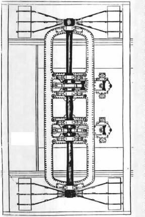
Fig.
128
The advantages proposed by these improvements
are simplicity of construction, more direct action on the crank, economy of
space and weight of material, combined with increased area of the piston,
whereby a given evaporating power of the boiler is rendered productive, by
extended application of the expansive principle, of a greater moving power than
in former arrangements. Consequently, under like circumstances, greater power
and economy of fuel is obtained, with the further advantage at sea in which the
engine is -reduced in its speed, either by the vessel being deeply laden with
coal, as is the case at the commencement of a long sea voyage, or by head
winds, more steam maybe given to the cylinders, and consequently more speed
imparted to the vessel, all the steam produced in the boiler being usefully
employed. (220.) Another improvement, having the same objects, and analogous to
the preceding, has likewise patented by Messrs. Maudslay and Field. This
consistent head options offer a cylinder of greater diameter, having two
piston-rods P V, u represented in)Fg.129., of considerable length, connected at
the top by a cross-head c. From this cross-head is carried downwards the
connecting rod D, which drives the crank-pin z, and thereby works the
paddle-shaft s. In this case the paddle-shaft is extended immediately above the
piston, and the double piston-rod has sufficient length to be above the
paddle-shaft when the piston is at the bottom of its stroke This improvement is
intended to be applied more particularly for engines for river navigation, the
advantages resulting from (221.) (223.) it being that a paddle-shaft placed at
a given height from the bottom of the vessel will be enabled to receive a
longer stroke of piston than by any other arrangement now in use.
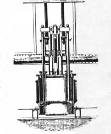
Fig.
129
A more compact and firm connection of the
cylinder with the crank-shaft bearings is effected by it, and a cylinder of
much greater diameter may be applied by which the expansive action of steam may
be more fully brought into play; and a more direct action of the steam-power on
the crank with a less weight of materials and a greater economy of space may be
obtained than by any of the arrangements of marine engines hitherto used.
(221.) Mr. Francis Humphrys has obtained a patent for a form of marine engine,
by which some simplification of the machinery is attained, and the same power
comprised within more limited dimensions. In this engine there is attached to
the piston of the cylinder, instead of a piston-rod, a hollow casing D D (fig.
130.), which moves through a stuffing-box G, constructed in a manner similar to
the stuffing-box of a piston-rod. In the figure, this casing is presented in
section, but its form is that of a long narrow slit, or opening, rounded at
either end as exhibited in the plan (fig.131) of the cylinder cover. The crank
c is driven by the other end of the connecting rod H, the crank-shaft being
immediately above the centre of the piston and the connecting rod passing
through the oblong opening D, and descending into the hollow piston-rod it is
attached to an axis I at the bottom of the piston. A box or cover K K encloses
the crosspiece or axis I with its bearings, and is attached so as to be
steam-tight to the bottom of the piston.
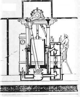
Fig.
130
A hollow space L is cut in the bottom of the
cylinder for the reception of the box K, when the piston is at the bottom of
the cylinder. By this arrangement the force by which the piston is driven in
its ascent and descent is communicated to the connecting rod, not, as usual,
through the intervention of a piston-rod, but directly from the piston itself
by the cross-pin I, from thence to the crank c, which it drives without the
intervention of beams, cross-heads, or any similar appendage. The slide-valves
regulating the admission and eduction of steam are represented at a; the rod of
the air-pump is shown at d, being worked by a crank placed on the centre of the
great crank shaft.* (222.) To obtain from the moving power its full amount of
mechanical effect in propelling the vessel, it would be necessary that its
force should propel, by constantly acting against the water in a horizontal
direction. and with a motion contrary to the course of the vessel. No system of
mechanical propellers has, however, yet been contrived capable of perfectly accomplishing
this. Patents have been granted for many ingenious mechanical combinations to
impart to the propelling surfaces such angles as appeared to the respective
contrivers most advantageous. In most of these mechanical complexity has formed
a fatal objection. No part of the machinery of a steam-vessel is so liable to
become deranged at sea as the paddlewheels; and, therefore, that simplicity of
construction which is compatible with those repairs which are possible on such
emerges is quite essential for safe practical use. The ordinary paddlewheel, as
has been already stated, is a wheel revolving upon a shaft driven by the
engine, and carrying upon its circumference a number of flat boards, called
paddle-boards, which we secured by nuts and braces in a fixed position is such
that the planes of the paddle-boards diverge nearly from the centre of the
shaft on which the wheel turns. The consequence of this arrangement is that
each paddle-board can only act in that direction which is most advantageous for
the propulsion of the vessel when it moves near the lowest point of the water.
In fig.132 let o be the shaft on which the common paddle-wheel revolves; the
position of the paddle boards are represented at A, b, c, &c. ; x, T
represents the water line, the course of the vessel being supposed to be from x
to Y ; the arrows represent the direction in which the paddlewheel revolves.
The wheel is immersed to the depth of the lowest paddle-board, since a ]en
degree of immersion would render a portion of the surface of each paddle-board
mechanically useless. In the position A, the whole force of the paddle board is
efficient for propelling the vessel ; but as the paddle enters the water in the
position H, its action upon the water, not being horizontal, is only partially
effective for propulsion: a part of the force which drives the paddle is in
depressing the water, and the remainder in driving it contrary to the course of
the vessel, and, therefore, by its reaction producing a certain propelling
effect. The tendency, however, of the paddle entering the water at ii, in to
form a hollow or trough, which the water, by its ordinary property, has a
continual tendency to fill up. After passing the lowest Point A, " the
paddle approaches the position is, where it emerges from the water, its action
again becomes oblique, a part only having a propelling effect, and the
remainder having a tendency to raise the water, and throw up a wave and spray
behind the paddlewheel.
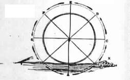
Fig.
132
It is evident that the more deeply the
paddlewheel becomes immersed, the greater, will be the proportion of the
propelling power that wasted in elevating and depressing the water; and if the
wheel were immersed to its axis, the whole force of the paddle-boards, on
entering and leaving the water, would be lost, no part of it having a tendency
to propel. If a still deeper immersion take place, the paddle-boards above the
axis, would have a tendency to retard the course of the vessel. When the vessel
is, therefore, in proper trim, the immersion should not exceed nor for short of
the depth of the lowest paddle; but for various reasons it is impossible in
practice to maintain this fixed immersion: the agitation of the surface of the
sea, causing the vessel to roll, will necessarily produce a great variation in
the immersion of the paddlewheels, one becoming frequently immersed to its
axle, while the other is raised altogether out of the water. Also the draught
of water of the vessel is liable to change, by the variation in her cargo; this
will necessarily happen in steamers which take long voyages. At starting they
are heavily laden with fuel, which as they proceed is gradually consumed,
whereby the vessel is lightened. (223) To remove this defect, and economics as
much as possible the propelling effect of the paddle-boards, it would them that
they may be necessary so to construct enter and leave the water edgeways, or as
nearly so as possible; such an arrangement would be, in effect, equivalent to
the process called feathering, as applied to oars. Any mechanism which would
perfectly accomplish this would cause the paddles to cause, and would very
nearly remove work in almost perfect silence the inconvenient and injurious
vibration which is produced by the action of the common paddles. But the
construction of feathering paddles is attended with great difficulty, under the
peculiar circumstances in which such wheels work. Any mechanism so complex that
it could not be easily repaired when deranged, with such engineering implements
and skill as can be obtained at sea, would be attended with great objections;
and the efficiency of its propelling action would not compensate for the
dangers which must attend upon the helpless state of a sterner, deprived of her
propelling agents.
Feathering paddle-boards must necessarily have
a motion independently of the motion of the wheel, since any fixed position
which could be given to them, though it might be most favourable to their
action in one position would not be so in their whole course through the water.
Thus the paddle board when at the lowest point should be in a vertical
position, or so placed that its plane, if continued upwards, would pass through
the axis of the wheel. lit other positions, however, as it passes through the
water, it should present its upper edge, not towards the wheel, but towards a
point above the highest point of the wheel. The precise point to which the edge
of the paddle-board should be directed is capable of mathematical
determination. But it will vary according to circumstances, which depend on the
motion of the vessel. The progressive motion of the vessel, independently of
the wind or current, must obviously be slower than the motion of the paddle
boards round the axle of the wheel; since it is by the difference of these
velocities that the reaction of the water is produced by which the vessel is
propelled. The proportion, however, between the progressive speed of the vessel
and the rotative speed of the paddle boards is not fixed: it will vary with the
shape and structure of the vessel, and with its depth of immersion ;
nevertheless it is upon this proportion that the manner in which the paddle
boards should shift their position must be determined. If the progressive speed
of the vessel were nearly equal to the rotative speed of the paddle-boards, the
latter should so shift their position that their upper edges should be
presented to a point very little above the highest point of the wheel. This is
a state of things which could only take place- in the case of a steamer. of a
small draught of water, scallop-shaped, and so constructed as to suffer little
resistance from the fluid. On the other hand, the. greater the depth of
immersion, and the less fine the lines of the vessel, the greater will be the
resistance in passing through the water, and the greater will be the proportion
which the rotative speed of the paddle-boards will bear to the progressive
speed of the vessel. In this latter case the independent motion of the paddle
boar should be such that their edges, while in the water, be presented towards
a point considerably above the highest point of the paddle wheel. A vast number
of ingenious mechanical contrivances have been invented and patented for
accomplishing the object just explained. Some of these have failed from the
circumstance of their inventors not clearly understanding what precise motion
it was meant to impart to the paddle board: others by which way for the paddle
wheel with movable paddles, which patent granted to Elijah Gal was purchased by
Mr. William Morgan, who made various alterations in the mechanism, not very
materially departing from the principle of the invention. This paddle wheel is
represented in fig. 133. The contrivance may be shortly stated to consist in
causing the wheel which began the paddles to revolve on one centre, and the
radial arms which move the paddles to revolve on another centre. A B C D E F 0
If I X L be the polygonal circumference of the paddle wheel, formed of straight
bars, secured connected together at the extremities of the spokes or radii of
the wheel which turns on the shaft which is worked by the engine; the centre of
this wheel being at O. So far this wheel is similar to the common paddle wheel;
but the paddle boards are not, as in the common wheel, fixed at A B C, so as to
be always directed to the centre u, but so placed that they are capable of
turning on an axis which are always horizontal, so that they can take any angle
with respect to the water which may be given to them. From the centre, or the
line joining the pivots on which these paddle-boards turn, there proceed short
arms K, firmly fixed to the paddle boards at an angle of about 120'. On a
motion given to this arm v., it will therefore give a corresponding angular
motion 0 the paddle board so as to make it turn on its pivots. At the extremities
of the several arms marked x is a pin or pivot, which the extremities of the
radial arms L are severally,attached, so that the angle between each radial L
and the short paddle-arm x is capable of being changed by any force imparted to
L; the radial arms are connected at the other lid with a centre, round which
they are capable of revolving. Now, since the points A B C, &c., which are
the pivots on which the paddle-boards turn, are moved in the circumference I f
a circle, of which the centre is o, they are always at the same distance from
that point; consequently they will continually vary their distance from the
other centre P. Thus, when a paddle-board arrives at that point of its
revolution at which the centre round which it revolves lies precisely be. I
faced it to the centre 0, its distance from the former centre 1 less than from
any other position. As it departs from that outside, its distance from that
centre gradually increases until it ,arrives at the opposite point of its
revolution, where the centre o is exactly between it and the former centre then
the distance of the paddle-board from the former centre is greatest.
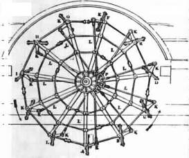
Fig.
133
This constant change of distance between each
paddle -board and the centre P is accommodated by the variation of the angle he
short paddle-board arm K; between the radial arm L and t -as. the paddle-board
approaches the centre, r this gradually diminishes; and as the distance of the
paddle-board increases, the angle is likewise augmented. This change in the
magnitude of the angle, which thus accommodates the varying position of the
paddle-board with respect to the centre P, will he observed in the figure. The
paddle-board D is nearest to P; and it will be observed that the angle
contained between L and K in there very acute; at B the angle between L and x
is to a right angle; increases, but is still acute ; at G it increases at H it
becomes obtuse; and at v., where it is most distant from the centre r, it
becomes most obtuse. It again diminishes, and becomes a right angle between A
and B. Now 14' this continual shifting of the direction of the short arm Y. is
necessarily accompanied by an equivalent change of position in the paddle-board
to which it is attached and the position of the second centre P is, or may be,
so adjusted that this paddle-board, as it enters the water and emerges from it,
shall be such as shall be most advantageous for propelling the vessel, and
therefore attended with less of that vibration which arises chiefly from the
alternate depression and elevation of the water, owing to the oblique action of
the paddle- (225.) In the year 1833, Mr. Field, of the firm of Maudslay and
field, constructed a paddle wheel with fixed paddle-boards, but each board
'being divided into several narrow slips arranged one a little behind the
other, u represented in fig. 134. These divided bows he proposed to arrange in
such cylindrical curves that they must all enter the 135. water at the same
place in immediate succession, avoiding the shock produced by the entrance of
the common board. These split paddle-boards are as efficient in propelling when
at the lowest point as the common paddle-boards, and when they emerge the water
escapes simultaneously front each narrow board, and is not thrown up, as is the
case with common paddle-
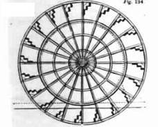
Fig.
134
The theoretical effect of this wheel is the
"me as that of the common wheel, and experience alone, the result of which
has not yet been obtained, can prove its efficiency. The number of bars, or
separate parts into which each paddle-board is divided, has been very various.
When first introduced by Mr. Galloway each board was divided into six or seven
parts-. this was subsequently reduced, and in the more recent wheels of this
form constructed for the government vessels the paddle-boards consist only of
two parts, coming as near to the common wheel as is possible, without
altogether abandoning the principle of the split paddle. (226.) To obtain an
approximate estimate of the extent to which steam-power is applicable to long
sea-voyages, it would be necessary to investigate the mutual relation which, in
the existing state of this application of steam-power, exists between the
capacity or tonnage of the vessel, the magnitude, weight, and power, of the
machinery, the available stowage for fuel, and the average speed attainable in
all
Field did not persevere in its use at the
time he invented it. It ban, however, been more generally adopted since the
date of Galloway' weathers, as well as the general purposes to which the vessel
is to be appropriated, whether for the transport Of goods or merchandise, or
merely for dispatches and passengers, or for combined. That portion of the
capacity of the both of these to the moving power consists of vessel which is
appropriated the fuel. The space occupied by the machinery and distribution of
it between these must mainly depend on the without length of the voyage which
the vessel must receiving a fresh supply of coal. if the trips be short, and
frequent relays of fuel can be obtained, then the space allotted to the
machinery may bear a greater proportion to that assigned to the fuel; but in
proportion as each uniform of interrupted stage of the voyage is increased, a
greater s a y less space left will be necessary, and a proportion for the machinery.
Other things being the same, therefore steam-vessels intended for long
sea-voyages must be less powerful in proportion to their tonnage. It will be
apparent that every improvement which takes place in the application of the
steam-engine to navigation win Me all these data on which shall an
investigation must depend Every increased efficiency of fuel, from whatever
cause it may be derived, will either increase the useful tonnage of the vessel,
or increase the length of voyage of which it is capable. Various improvements
have been and are still in progress, by which the efficiency has undergone
continual augmentation, and voyages may now be accomplished with moderate
economy and profit, to which a few years since marine engines could not be
applied with permanent advantage. The average speed of steam-vessels has
undergone a gradual increase by such improvements. During the four years ending
June, 1834, it was found that from fifty-one voyages the average rate of
steaming obtained made by the Admiralty steamers between Falmouth and Corfu,
exclusive of stoppages, was seven miles and a quarter an hour direct distance
between port and port. The vessels which performed this voyage varied from 350
to 700 tons measured burden, and were provided with engines varying from 109 to
200 horsepower, with stowage for coals varying from 80 to 240 tons. The
proportion of the power to the
A linkage varied from one horse to three tons
to one horse to many have already. stated that the nominal horsepower is
extremely indefinite; and if, as is now customary in a longer class of voyages,
the steam be worked exponentially then the nominal power almost ceases to have
any C, higher relation to the actual performance of the vessel. It is usual to
calculate the horsepower by assuming a firm pressure of steam upon the piston,
and, consequently, I excluding the consideration of the effect of expansion.
;The most certain test of the amount of mechanical power asserted by the
machinery would be obtained from the quality of water actually transmitted in
the form of steam from II c boiler to the cylinder. But the effect of this
would also be influenced by the extent to which the expansive principle has
been brought into operation. From the reported performances of the larger class
of high action ships within the last few years, it would appear that average
speed has been consistent since the estimate L above mentioned, which was
obtained in 1834; and on the consumption of fuel with the actual performance,
it would appear that the efficiency of fuel has also been considerably
augmented. No extensive course of accurate lists or observations have, however,
been obtained in which correct inferences may be drawn. Of the probable things
steam navigation, in its present state, is being extended. The jealousy of
rival companies is obstructing the junctions of those who, solicitous swore.
for the general advancement of the art than for the success of individual
enterprises, have directed their attention to this question ; and it is hardly
to be expected that sufficiently correct and extensive data call be obtained
for this purpose. (227.) Increased facility in the extension and application of
steam-navigation is expected to arise from tile substitution of iron for wood,
in die construction of vessels. Therefore iron steamers have been chiefly
confined to river-navigation; but there appears no sufficient reason why their
use should be thus limited. For sea-voyages they offer many advantages; they
are not half the weight of vessels of equal tonnage constructed of wood; and,
consequently, with the same tonnage they will have less draught of water, and
therefore less resistance to the propelling power; or, with the same draught of
water and the same resistance, they will carry a proportionally heavier cargo.
The nature of their material renders. them more stiff and unyielding than
timber; and they do not suffer that effect which is called hollow, which arises
from a slight alteration which takes place in the figure of a timber vessel in
rolling, accompanied by an alternate opening and closing of the seams. Iron
vessels have the further advantage of being more proof against fracture upon
rocks. If a timber vessel strike, a plank is broken, mid a chasm opened in her
many times greater than the point of rock which produces the concussion. If an
iron vessel strike, she will either severely receive a blow, or be pierced by a
hole equal in size to the point of rock which she encounters. Some examples of
the strength of iron vessels were given by Mr. Macgregorard, in his evidence
before the Committee of the Commissioners on Steam Navigation, among which the
following may be mentioned - - iron vessel, called the ALBUITKAII, ill One of
their experimental trials got aground, and lay upon her anchor: in a wooden
vessel the anchor would probably have pierced her bottom ; in this case,
however-, tile bottom was only damaged. All iron vessel, built for the Irish
Inland Navigation Company, works being, towed across Lougli Derg it, it gale of
wind, when the towing rope broke, and she was driven upon rocks, on which site
bumped for a considerable time without any injury. A wooden vessel would in
this case five gone to pieces. A further advantage of iron vessels ,which in
warm climates is deserving of consideration is their better coolness and
perfect freedom from vermin. Iron steam-vessels on a very large scale are now
in preparation in the ports of Liverpool and Bristol, intended for long
sea-voyages. The largest vessel of this description which has yet been
projected is stated to be in preparation or the voyage between Bristol and New
York, by the company any who have established the steamship called the Great
Eastern, plying between these places.
Several projects for the extension of
steam-navigation to voyages of considerable length have lately been entertained
both by the public and by the legislature, and have imparted sincere attempt to
improve steam-navigation increased interest. A committee of the House of
Commons collected evidence and made a report in the last session in favour of
an experiment to establish a line of steam-communication between Great Britain
and India. Two routes have been suggested by each committee, each being a
continuation of the line of Admiralty steam-packets already established to
Malta I the Ionian Isles. One of the routes proposed is through the Red Sea,
and across the Indian Ocean to Bombay, some Of the older presidencies ; the
other across the north to , banks of the Euphrates, by that river to the
Persian Gulf, and from thence to Bombay. Each of these routes will be attended
with peculiar difficulties, and in a long sea-voyage will be encountered. In
the route by the Red Sea it is proposed to establish relations between Malta
and Alexandria (eight hundred and eighty miles). A steamer of four hundred
tons' burden and two hundred horsepower would perform this voyage, upon average
of all weather incident to the situation, in from five to six days, consuming
ten tons of coal per day. But it is probable that it might be found more
advantageous to establish a higher ratio between the power and the tonnage.
From Alexandria the transit might be effected by land across isthmus to Suez -
a journey of from four to five days by caravan and camels; or the transit Ought
be made either by land or water from Alexandria to Cairo, a distance of one
hundred and seventy-three miles; and from-Cairo to Suez, ninety-three miles,
across the desert, in about- five days. At Suez would be a station for
steamers, and the Red Sea would be traversed in three runs or more. If necessary,
stations for coals might be established at Cosseir, Judda, Mocha, and finally
at Aden or at Socatra - an island immediately beyond the mouth of the Red Sea,
in the Indian Ocean;. the run from Suez to Cosseir would be three hundred miles
- somewhat more than twice the distance from Liverpool to Dublin. From Cosseir
to Judda, four hundred and fifty miles; from Judda to Mocha, five hundred and
seventeen miles; and from Mocha to Socatra, six hundred and forty-two miles. It
is evident that all this would, without difficulty, in the most powers of
unfavourable weather, fall within the present steam-navigation. If the terminus
of the passage be Bombay, the run from Socatra to Bombay will be twelve hundred
miles, which would be from six to eight days' steaming. The whole passage from
Alexandria to Bombay, allowing three days for delay between Suez and Bombay,
would be twenty-six days; the time from Bombay to Malta would therefore be
about thirty-three days; and adding fourteen days to for the transit from Malta
to England, we should -seven days from London to Bombay, or have a total of
forty loft about seven weeks.
If the terminus proposed were - Calcutta, the
course from Socratra would be one thousand two hundred and fifty miles
southeast to the Maldives, where a station for coals would be established. This
distance would be equal to that from Socatra to Bombay. From the Maldives, a
run hundred miles would reach the southern point of Ceylon, called the Point de
Galle, which is the best harbour (Bombay excepted) in British India: from the
Point de Galle, a run of six hundred miles will reach Madras, and from Madras
to Calcutta would be a run of about six hundred unites. The voyage from London
to Calcutta would be performed in about sixty days.
At a certain season of the year there exists
a powerful physical opponent to the transit from India to Suez: frontthe middle
of June until the end of September, the southwest monsoon blows with unabated
force across the Indian Ocean, and more particularly between Socatra and
Bombay. This wind is so violent as to leave it barely possible for the most
powerful steam-packet to make head against it, and the voyage could not be
accomplished without serious wear and tear upon the vessels during these
months. The attention of parliament has therefore been directed to another line
of communication, not liable to this difficulty-. it is proposed to establish a
line of steamers from Bombay through the Persian Gulf to the Euphrates. The run
from Bombay to a place called Muscat, on the southern shore of the gulf, would
be eight hundred and forty miles in a northwest direction, and therefore not
opposed to the south-west monsoon. From Muscat to Bassidore, a point upon the
northern coast of the strait at the mouth of the Persian Gulf, would be a run
of two hundred and fifty-five miles ; from Bassidore to Bushire, another point
on the eastern coast of the Persian Gulf, would be a run of three hundred miles
; and from Bushire to the mouth of the Euphrates, would be one hundred and
twenty miles. It is evident that the longest of these runs would offer no more
difficulty than the passage from Malta to Alexandria. From Bussora, near the
mouth of the Euphrates, to Bir, a town upon its left bank near Aleppo, would be
one thousand one hundred and forty-three miles, throughout which there are no
physical obstacles to the river-navigation which may not be overcome. Some
difficulties arise from the wild and savage character of the tribes who occupy
its banks. It is, however, thought that by proper measures, and securing the
cooperation of the pacha of Egypt, any serious obstruction from this cause may
be removed. From Bir, by Aleppo, to Scanderoon, a port upon the Mediterranean,
opposite Cyprus, is a laid-journey, Raid to be attended with some difficulty,
but not of great length; and from Scanderooti to Malta is about the same
distance as between the latter place and Alexandria. It is calculated that the
time from London to Bombay by the Euphrates- supposing the passage to be
successfully established-would be a few days shorter than by Egypt and the Red
Sea. Whichever of these courses may be adopted, it is clear that the
difficulties, so far as the powers of the steam engine are concerned, lie in
the one case between Socatra and Bombay or between Socatra and the Maldives,
and in the other case between Bombay and Muscat. This, however, has already
been encountered and overcome on four several voyages by the Hugh Lindsay to
Suez : that the from Bombay vessel encountered a still longer run on these
several trips, by going, not to Socatra, but to Aden, a point on the coast of
Arabia, near the Straits of Babel Mandeb, being a run of one thousand six
hundred and forty-one miles, which she performed in ten clays and nineteen
hours. The same trip has since been repeatedly made by other steamers; and, in
the present improved state of steam navigation, no insurmountable obstacles are
opposed to their passage.
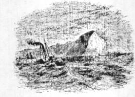
CHAP.
XIV
AMERICAN
STEAM NAVIGATION.
STEAM NAVIGATION FIRST ESTABLISHED IN
AMERICA.- CIRCUMSTANCES WHICH LED TO IT.- FLICH AND HUMSEY.- STEVENS OF
HOBOKEN- LIVINGSTONE AND FULTON- EXPERIMANTS ON THE SEINE- FULTON'S FIRST BOAT-
THE HUDSON NAVIGATED BY STEAM- EXTENSION AND IMPROVEMENT OF RIVER NAVIGATION-
SPEED OF AMERICAN STEAMERS. .
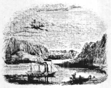
(228) The credit of having afforded the first
practical solution of the problem to apply the steam engine to the propulsion
of ships, undoubtedly belongs to the people of United States of America. The
geographical character of the vast country, not less than the sanguine and enterprising
spirit of the nation, contributed to this. A coast of four thousand miles in
extent, stretching from the Gulf of St. Lawrence to the embouchures of the
Mississippi, indented and serrated in every part with natural harbors and
sheltered bays, and fringed with islands forming sounds -capes, and
promontories enclosing arms of the sea, in which the waters are free from the
roll of the ocean, and take the placid character of lakes, rivers of imposing
magnitude, navigable for vessels of the, largest class, for many hundreds and
in some instances for many thousands of miles, affording access to the
innermost population of an empire, whose area vastly exceeds the whole European
continent,-chains of lakes composed of the most extensive bodies of fresh water
in the known world, and this extensive continent peopled by races carrying with
them the habits and feelings together with much of the &kill and knowledge
of the most civilized parts of the globe, endowed also with that
inextinguishable spirit of enterprise which ever belongs to an emigrant people,
form a combination of circumstances more than sufficient to account for the
fact of this nation snatching from England, the parent of the steam engine, the
honour of first, bringing into practical operation one of the most important if
indeed it be not altogether the most important of the many applications of that
machine to the uses of life. The circumstances which rendered these extensive
tracts of inland and coast navigation eminently suited to the application of
steam power, formed so many obstructions and difficulties to the application of
other more ordinary means of locomotion on water. The sheltered bays and sounds
which offered a smooth and undisturbed surface to the action of the infant
steamer argued the absence of that element which gave effect to the sails and
rigging of the wind-propelled ship, and the rapid currents of the gigantic
streams formed by the drainage of this great continent, though facilitating
access to the coast, rendered the oar powerless in the ascent. (229.) The first
great discovery of Watt had scarcely been realized in practice by the
construction of the single-acting steam-engine, when the Speculative and
enterprising Americans conceived the project of applying it as a moving power
in their inland navigation. So early as the year 1783 Fitch and Rumsey made
attempts to apply the single-acting engine to the propulsion of vessels, and
their failure, is said to have arisen more from the inherent defects of that
machine in reference to this application of it, than from any want of ingenuity
or mechanical skill on their parts. In 1791, John Stevens of Hoboken commenced
his experiments on steam navigation, which were continued for sixteen years;
during a part -of this period he was assisted by Livingstone (who was
subsequently instrumental in advancing the views of Fulton), and by Roosevelt.
These projectors had, at that time also, the assistance and advice of Brunel,
since so celebrated for the invention of the block )machinery, and the construction
of the Thames Tunnel. Their proceedings were interrupted by the appointment of
Livingstone as American Mister at Paris, under the Consular Government. At
Paris, Livingstone met Fulton, who had been previously engaged in similar
speculations, and being struck with his mechanical skill, And the soundness of
his views, joined him in causing a series of experiments to be made, which were
accordingly carried on at Plombi6res, and subsequently on a still more
extensive scale on the Seine, near Paris. Having by this course of experiments
obtained proofs of the efficiency of Fulton's projects, sufficient to satisfy
the mind of Livingstone, he agreed to obtain for Fulton the funds necessary to
construct a steam boat on a large scale, to be worked upon the Hudson. It was
decided, in order to give the project the best chance of success, to obtain the
machinery from Bolton and Watt. In 1803, Fulton accordingly made drawings of
the engines intended for this first steamer, which were sent to Soho, with an
order for their construction. Fulton, rnean while, repaired to America, to
superintend the construction of the boat. The delays incidental to these
proceedings retarded the completion of the boat and machinery until the year
1807, when all was completed, and the first successful experiment' made at New
York. The vessel was placed, for regular work, to ply between' New York and
Albany.),, in the beginning of 1808; and, from that time to this present, this
river has been the theatre of the most remarkable series of experiments on
locomotion on water which has ever been presented in the history of navigation.
(230.) The form and arrangement of this first
marine engine was, in many respects, similar to that which is still generally
used for marine purposes. The cold water cistern was abandoned, and an
increased condensing power obtained by enlarging the condenser. It was usual to
make the condenser half the diameter of the cylinder, and half its length, and
therefore one eighth of its capacity The condenser, however, was now made of
the same diameter as the cylinder, being still half its length; its capacity
therefore, instead of being only an eighth, was half of the cylinder; the
condensing jet by a pipe passing through the bottom of the vessel. As in the
present marine engines, two working beams were provided, one at either side of
the cylinder; but in order to provide against the difficulties which might
arise in the adaptation of machinery made at Birmingham to a vessel made at New
York, beams were constructed in the form of an inverted I, the working arms
being twofold, one horizontal and the other vertical, so that the connecting
rod might be sea from the crank, either downwards, to the end of the horizontal
arm, or horizontally, to the end of the vertical arm. In fact there was a
choice, to use either a straight beam, or a bell-crank. The latter was that
which was adopted in this instance. The paddle-shaft, driven by the crank,
passed across the vessel, and had the paddle-wheels keyed upon it as at
present; and in order to equalise the effect of the engine spur wheels were
also placed on the paddle-shaft, by which pinions were driven, placed upon an
axle, which carried flywheel. The speed attained by this steam boat, when it
first began to ply upon the river, did not exceed four miles an hour, but by a
series of improvements its rate of motion was soon increased to six miles an
hour. in the steam boats subsequently constructed by Fulton a greater speed was
attained; but in the latest vessels built by him he did not exceed a speed of
nine miles an hour, which be considered to be the greatest that could be
advantageously obtained. While Fulton was making his plans, and engaged in the
construction of his first boat, Mr. Stevens of Hoboken, already mentioned, was
engaged in a like project, and completed a vessel, to be propelled by a steam
engine, within a few weeks after the first successful voyage of Fulton. Stevens
was likewise completely successful; but the exclusive .privilege of navigating
the Hudson by steam having been granted to Fulton by an act of Congress,
Stevens was compelled to select another theatre for his operations, and he
accordingly sent his steam boat by sea to Philadelphia, to navigate the
Delaware, thus securing for himself the honour of having made the first sea
voyage by steam. Fulton did not long retain the monopoly of the steam
navigation of the Hudson. Fortunately for the progress of steam navigation, the
act conferring upon him that privilege was declared unconstitutional; and the
navigation of that noble river was thrown open to the spirit and enterprise of
American genius. The number of passengers conveyed upon it became enormous
beyond all precedent, and inducements of the strongest kind were accordingly
held out to the improve-ment of its navigation. The distance between New York
and Albany, ascertained by a late survey to be one hundred and twenty-five
geographical miles by water had been performed by Fulton boats occasionally in
fifteen or sixteen hours, being at the rate of about 'eight miles an hour,
including stoppages. It became a great object to increase the speed of this
trip, so that it might 4#t all times of the year be performed between sunrises
and sunset. Robert L. Stevens, the son of the person of that name already
mentioned, immediately after the abolition of Fulton's monopoly, placed on the
river a vessel which had been built for the Delaware, which easily performed
the' passage in twelve hours, being at the rate of nearly ten and a half
geographical miles an hour. By this increase of speed the improved boats.3o
entirely monopolised the day work upon the river, that the former steamers were
either converted into steam tugs to draw barges laden with goods, or used for
night trips between New York- and Albany. In the night trips the saving of one
or two hours was immaterial, it being sufficient that the vessel which left the
one port at night should reach the other in the morning.
The river Hudson rises near Lake Champlain,
the easternmost of the great chain of lakes or inland seas which extend from
east to west across the northern boundary of the United States. The river
follows nearly a straight course southwards for two hundred and fifty miles,
and empties itself into the sea at New York. The influence of the tide is felt
as far as Albany, above which the stream begins to contract. Although this
river in magnitude and extent is by no means equal to several others which
intersect the States, it is nevertheless rendered an object of great interest
by reason of the importance and extent of its trade. The produce of the state
of New York and that of the banks of the great Lakes Ontario and Erie are
transported by it to the capital; and one of the most extensive and populous
districts of the United States is supplied with the necessary imports by its
waters. A large fleet of vessels is constantly engaged in its navigation; nor
is the tardy but picturesque sailing vessel as yet excluded by the more rapid
steamers. The current of the Hudson is said to average nearly three miles an
hour; but as the ebb and flow of the tide are felt as far as Albany, the
passage of the steamers between that place and New York may be regarded as
equally affected by currents in both directions, or nearly so. The passage
therefore, whether in ascending or descending the river, is made nearly in the
same time. (231.) The prevalence of smooth water navigation, whether on the
surface of rivers or in sheltered bays and sounds, has invested the problem of
steam navigation in America with conditions so entirely distinct and different
from those under which the same problem presents itself to the European
engineer, that any comparison of the performance of vessels, Whether with
regard to speed or the absorption of power in the two cases, must be utterly
fallacious. In Europe a steamer is almost invariably a vessel designed to
encounter tile agitated surface of an open sea, and is accordingly constructed
upon principles of suitable strength and stability. It is likewise supplied
with rigging and with sails, to be used in aid of the mechanical power, and
manned and commanded by experienced seamen ; in fact, it is a combination of a
nautical and mechanical structure. In America, on the other hand, with the
exception of the vessels which navigate the great northern lakes, the steamers
are structures exclusively mechanical, being designed for smooth water. They
require no other strength or stability than that which is sufficient to enable
them to float and to bear a progressive motion through the water. Their mould
is conceived with an exclusive view to speed; they are therefore slender and
weak in their build, of great length in proportion to their width, and having a
very small draugbt of water. In fact, they approach in their form to that of a
Thames wherry on a very large scale. The position and form of the machinery is
likewise affected by these conditions. Without the necessity of being protected
from a rough sea, it is placed on the deck in an elevated position. The
cylinders of large diameter and short stroke invariably used in Europe are
unknown in America, and the proportions are reversed, a small diameter and
stroke of great length being invariably adopted. It is rarely that two engines
are used. A single engine, placed in the centre of the deck, with a cylinder
from forty to sixty inches' diameter, and from eight to ten foot stroke, drives
paddle-wheels from twenty-one to twenty-five feet in diameter, producing from
twenty-five to thirty revolutions per minutes The great magnitude of the
paddle-wheels and the velocity impacted to them enable them to perform the
office of fly-wheels, and to carry the engine round its centres, not however
without a perceptible inequality of motion, which gives to the American steamer
an effect like that of a row boat advancing by starts with each stroke of the
piston, The length of stroke adopted in these engines enables them to apply
with great effect the expansive principle, which is almost universally used,
the steam being generally cut off at half stroke.
The steamers which navigate the Hudson are
vessels of considerable magnitude, splendidly fitted up for the accommodation
of passengers they vary from one hundred and eighty to two Hundred and forty
feet in length, and from twenty to thirty feet in width of beam In the
following table is given the particulars of nine steamers plying on this river,
taken from
494 THE STEAM ENGINE.
NAME
Length
Breadth Draft Drain
Length Depth Num. Drain
of
Deck of Beam of Water of Wheel of Paddles of
Paddles of Engs.
of Cyl.
Ft. Ft.
Ft. Ft. Ft. Ft.
Ft. Ft.
Clinton
230 28 5’5 21 13’7
36 1
65
Champlain
180 27 5’5 22 15
34
2 44
Erie
180
27 5’5 22 15
34 2
44
N.
America 200 30 5 21 13 30 2
44’5
Independence
148 26
/ / / /
1
44
Albany
212 26 / 24’5 14
30 1
65
Swallow
233 22’5 3’75 24
11 30 1 46M
Rochester
200 25 3’75 23’5 10 24 1 43
Utica
200
21 3’5 22 9’5
24 1
39
The hulls of these boats are formed with a perfectly
flat bottom and perpendicular sides, rounded at the angles, as represented in
fig. 135. At the bow, or cutwater, they are made very sharp, and the deck projects to a great distance
over the sides. The weight of the machinery is distributed over an extensive
surface of the bottom of this feeble structure, by means of a framework of
substantial carpentry to which it is attached. At the height of from four to
six feet above the water-line is placed the deck, which is a platform, having
the shape of a very elongated ellipse.
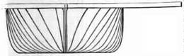
Fig.
135
The extremities of its longer axis are
supported by the sternpost and tile cutwater, and its sides expand in gentle
curves on either hand to a considerable distance beyond the limits of the hull;
those parts of the deck thus overhanging the water are - called the wheel
guards. Beneath the first deck is the saloon, or dining-room, which also, as is
usual in European ' steamers, forms the gentlemen's sleeping-room. It usually
extends from end to end of the vessel. The middle of the first deck is occupied
by the engine, boilers, furnaces, and chimneys, of which latter there are
generally two. , Between tile chimneys and the stern, above the first deck, is
constructed the ladies cabin, which is covered by the second deck, called the
promenade deck. The great length of these boats and, the elevation of tile
ethnic.,, render it impossible for a steersman at the stern to see ahead, and
they are, consequently, steered front the bow: the wheel placed there
communicating with the hull at the stern, by chains or rods carried along the
sides of the boat. Until a recent period, the wheel was connected with the
stern by ropes, but some fatal accidents, produced by fire, in which these--
ropes were burnt, and the steersman lost all power to guide the vessel, caused
metal rods or claims to be substituted. (232.) The paddle-wheels universally
used in American steam-boats are formed, as if by the combination of two or
more common paddle-wheels, placed one outside the other, on the same axle, but
so that the paddle boards of each may have an intermediate position between
those of the adjacent one, as represented in fig.136
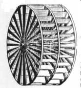
Fig.
136
The spokes, which are bolted to cast-iron
flanges, are of wood. These flanges, to which they are so bolted, are keyed
upon the paddle shaft. The outer extremities of the spokes are attached to
circular bands of iron, surrounding the wheel; and the paddle boards, which are
formed of hard wood, are bolted to the spokes. The wheels thus constructed,
sometimes consist of three, and not infrequently four, independent circles of
paddle boards, placed one beside the other, and so adjusted in their position,
that the boards of no two divisions shall correspond.
The great magnitude of the paddle-wheels, and
the circumstance of the navigation being carried on, for the most part, in
smooth water, have rendered unnecessary, in America, the adoption of any of
those expedients for neutralising the effects of the oblique action of the
paddles, which have been tried, but hitherto wit], so little success, in
Europe.
Sea going steamers arc not numerous the chief
of them being those which ply between New York and Providence, and between New
York and Charleston. These vessels, however, do not reliable the sea-going
steamers of' Europe as closely is ,night be expected; and to the latter, the
sea-going steamers of America can hardly be regarded as safe means of
transport.
The Narragement, the finest of these vessels,
is built of oak, strengthened by diagonal straps or ties of iron, by which her
timbers are connected; site is driven by a condensing engine, and has two
boilers, exposing about three thousand square feet of surface to the fire. The
steamer is maintained at a pressure of twenty to twenty-five tbs. per square
inch: the cylinder is Horizontal. The cabins of these sea-boats are of great
magnitude, and offer excellent accommodation for containing generally four
hundred berths.In the Massachusetts the chief cabin is one hundred and sixty
feet long, twenty-two feet wide, and twelve feet in length, its vast extent
being uninterrupted by pillars or any other obstruction. ,I have dined,"
says Stevenson, with one hundred seventy persons five ion this cabin not
withstanding this numerous assembly, the tables which were arranged in two parallel
rows. There are on hundred and twelve fixed berths can be erected in the middle
of the floor: besides these there are sixty fixed berths in the ladies' cabin
and several temporary sleep ing places can be erected in it also. The cabin of
the Massachusetts is by no means the largest in the United States. Some
steamers have cabins upwards of one hundred and seventy-five feet in length.
Those large saloons are lighted by Argaild lamps, suspended from the ceiling,
and their appearance, when brilliantly lighted up and filled with company, is
very remarkable. The passengers generally exchange themselves in parties at the
numerous small tables into which the large tables are converted after dinner,
and engage in different amusements. The scene resembles much more the
coffee-room of some great hotel than the cabin of a floating vessel."
(234.) Nothing has excited more surprise among engineers and others interested
in steam navigation in Europe, than the statements which have been so generally
and so confidently made of the speed attained by American steamers. This
astonishment is due to several causes, the chief of which is the omission of
all notice of the great difference between the structure and operation of the
American steamers and the nature of the navigation in which they are engaged,
compared with the structure and operation of, and the navigation in which
European steamers are employed: as well might the performance of a Thames
wherry, or one of the fly-boats on the northern canals, be compared with that
of the Great Western, or the British Queen. The statements alluded to all have
reference to steamers navigating the Hudson between New York and Albany, the
form and structure of which we have already described; and doubtless the
greatest speed ever attained on the surface of water has been exhibited in the
passages of these vessels. Mr. Stevenson states, that exclusive of the time
lost in stoppages, the voyage between New York and Albany is usually made in
ten hours. Dr. Renwick, however, who has probably more extensive opportunities
of observation, states, that the average time, exclusive of stoppages, is ten
hours and a half. The distance being 125.18 geographical miles, the average
rate would therefore be 11 9/10 miles per hour, If it be observed that the
average rate of some of the best sea-going steamers in Europe obtained from
experiments and observations made by myself, more than three years ago, showed
a rate of steaming little less than ten geographical miles per hour, and that
since that time considerable improvements in steam navigation have been made,
and further, that these performances were made under exposure to all the
disadvantages of an open sea, the difference between them and the performance
of the American river steamers will cease to create astonishment. Dr. Renwick
states that be made, in a boat called the 46 New Philadelphia," one of the
most remarkable passages ever performed. He left New York at five in ' the
afternoon, with the first of the flood, and landed at Catskill, distant 95-8
geographical miles from New York, at a quarter before twelve. Passengers were
landed and taken in at seven intermediate points: the rate, including
stoppages, was therefore 14-2 miles per hour; and if half all hour be allowed
for stoppages, tile actual average rate of motion would be fifteen miles and
three quarters all hour. As the current, which in this case was with the course
of the vessel, did not exceed three miles and a half an hour, the absolute
velocity through the water would have been somewhat under twelve miles an hour.
This speed is nearly the same as the speed obtained from taking the average
time of the voyages between New York and Albany at ten hours and a half ; it
would therefore appear that the great speed attained in this trip must have
been chiefly, if not altogether, owing to the effect of the current. (235.) The
steamers which navigate the great northern lakes differ so little in their
construction and appearance from the European steamboats, that it will not be
necessary here to devote any considerable space . to an account of them. These
vessels were introduced oil the lakes at about the same time that steamers were
first introduced oil the Clyde. These steamers are strongly built vessels,
supplied with sails and rigging, and propelled by powerful engines. The largest
in 1837, when Mr. Stevenson visited the States, was the James Madison. This
vessel was one hundred and eighty one feet in length on the deck, thirty feet
in breadth of beam, and twelve feet six inches in depth of hold: her draught of
water was ten feet, and her measured capacity seven hundred tons. She plyed
between Buffalo on Lake Brie and Chicago Lake Michigan, a distance of nine
hundred and fifty miles The severe storms and formidable sea encountered on the
lakes render necessary for tile navigation, vessels in all respects as strong
and powerful us those which navigate the open ocean. (M.) By for the most
remarkable and important of all the American rivers at the Mississippi and
distributors. That part of the American continent which extends from the
southern shores of the great northern lakes t o tile northern shores of the
Gulf of Mexico, is watered by these great streams. The main stream of the
Mississippi has its fountains in the tract of country lying north of the Illinois
and east of Lake Michigan, in latitude forty-three degrees. At about latitude
thirty nine degrees, a little north of St. Louis, it receives the waters of the
Missouri, and further south, at the latitude of thirty seven degrees, the Ohio
flows into it, after traversing five degrees of longitude and four of latitude,
and winding its way from the Alleghany ranged through several of the states,
and forming a navigable communication with numerous important towns of the
Union, among which may be mentioned Pittsburgh, Cincinnati, Frankfort,
Lexington, and Louisville. The. Main stream of the Mississippi, after receiving
the waters of the Arkansas, and numerous other minor tributaries, flows into
the Gulf of Mexico by four months. The main stream of the Mississippi,
independently of its tributaries, forms an unbroken course of inland navigation
file r a distance of nearly two thousand three hundred miles. Its width,
through a distance of one thousand one hundred miles from its mouth, is not
less than half a mile, and its average depth a hundred feet. The Ohio, its
chief eastern tributary, flowing into it at a distance of about a thousand
miles, from its mouth, traverses also about the same extent of country, and is
navigable throughout the whole of that extent. This river also has several
navigable tributaries of considerable extent, among which May be mentioned the
Muskingum, navigable for one hundred and twenty miles ;'the Miami, navigable
for seventy five miles; the Scioto, navigable for one hundred and twenty miles;
the Tennessee, navigable for two hundred and fifty miles; the Cumberland,
'navigable for four hundred end forty miles; the Kentucky, navigable for one
hundred and thirty miles; and the Green River, navigable for one hundred and
fifty miles. The total length of the Ohio and its tributaries estimated at
above seven thousand miles. (237.) Steam-boats were introduced on the
Mississippi about the year 1812, the period of their first introduction in
Europe; and their increase has been rapid beyond all precedent. In the year
1831 there were one hundred and ninety, eight steamers plying on its waters;
and the number in 1837 amounted to nearly four hundred. These vessels are built
chiefly on the banks of the Ohio, at the towns of Pittsburgh and Cincinnati, at
distances of about two thousand miles from the mouth of the river they are
intended to navigate. (238.) These steamers, which are decidedly inferior to
those which navigate the eastern water, are generally of a, heavy build, fitted
to carry goods as we as passengers,. and vary from one hundred to seven hundred
tons berths. Their draught of water is also greater than that of the eastern
river steamer varying from sixty eight feet. The hull about five feet from the
water line, is covered with a deck, under which is the hold, in which the heavy
part of the is stowed. About the, middle of this deck the engines are placed,
the boilers and furnaces occupying a t; pace nearer to the bow, near which deck
chimneys are placed. The fire, doors of the furnaces are presented towards the
bow, and exposed so as to increase the draught. That part of the first deck
which extends from the machinery to the stern is the place allotted to the crew
and the deck passengers, and is described as being filthy and inconvenient in the
extreme. second deck is constructed, -which extends from the chimneys near the
bow to the stern of the vessel. On this is formed the great cabin or saloon,
which extends from the chimney* to within about thirty feet of the stern, where
it is divided by a horizontal from the ladies ladies' cabin, which occupies the
remaining space. These principal cabins are surrounded by a gallery about three
feet in width, from which, at convenient places, an ascent is supplied by
stairs to the highest deck, called the hurricane or promenade deck. (239.) The
engines by which these boats are propelled are totally different from the
machinery already described as used in the eastern steamers. They are
invariably non-condensing engines, worked by steam of extremely high pressure;
'the boilers are therefore tubular, and the cylinders small in diameter, but
generally having a long stroke. The pressure of steam used in these machines is
such as is never used in European engines, even when worked on railways. A
pressure of one hundred pounds per inch is here considered extremely moderate.
The captain of one of these -boats, plying between Pittsburgh and St. Louis,
told Mr. Stevenson that 11 under ordinary circumstances his safety valves were
loaded with a pressure equal to one hundred and forty-eight pounds per square
inch, but that the steam was occasionally raised as high as one hundred and
fifty pounds to enable the vessel to pass parts of the river in which there is
a strong current ;'! and he added, by way of consolation, that 01 this pressure
was never exceeded except on extraordinary occasions I" The dimensions and
power of the Mississippi steamers may be collected from those of the St. Louis,
a, boat which was plying on that river in 1837. That vessel measured two hundred
and fifty feet on deck, and had twenty-eight feet breadth of beam. Her draught
of water was eight feet, and her measured capacity one thousand tons. She was
prepared by two engines with thirty-inch cylinders, and ten feet stroke; the
safety valve being loaded at one hundred pounds per square inch. The paddle
wheels of these vessels are attached to the paddle shaft, in such a manner as
to be thrown into and out of gear, at discretion, by the engineer, so that the
paddle shaft may revolve without driving the wheels: by the expedient the power
of the engine is used to feed the boilers while the vessel stops at the several
stations. The vessel is therefore stopped, not, as is usually the case, by
stopping the engines, but by throwing the wheels out of connection with the
paddle shaft. The engines continue to work, but their power is expended in
forcing water into the boiler. By this expedient the activity of the engines
may, within practical limits, be varied with the resistance the vessel has to
encounter. In working against 4 strong current, the feed may be cut off from
the boilers, and the production of steam, and consequently the power of the
engines, thereby stimulated, while suspension of the feed may be compensated at
the
next station. The stoppages to take in goods
and passengers, and for relays of fuel, are frequent. 91 The liberty which they
take with their vessels on these occasions," says Mr. Stevenson, 41 is
somewhat amusing: I had a good example of this on board a large vessel, called
the Ontario. She was steered close in shore amongst stones and stumps of trees,
where she lay for some hours to take in goods: the additional weight increased
her draught of water, and caused her to heel a good deal; and when her engines
were put in motion, she actually crawled into the deep water on her paddle
wheels: the steam had been got up to an enormous pressure to enable her to get
off, and the volume of steam discharged from the escarpment pipe at every half
stroke of the piston made a sound almost like the discharge of fire-arms, while
every timber in the vessel seemed to tremble, and the whole structure actually
groaned under the shocks." Besides the steamers used for the navigation of
the Mississippi, innumerable steam tugs are constantly employed for towing
vessels between the port of New Orleans and the open sea of the Gulf of Mexico.
Before the invention of steam navigation, this southern capital of the United
States laboured under the disadvantage of possessing almost the only bad and
inconvenient harbour in the vast range of coast by which the country is
bounded. New Orleans lies at a distance of about one hundred miles from the
Gulf of Mexico. The force of the stream, the frequency of shoals, and the
winding course of the channel rendered it scarcely possible for a sailing
vessel to pass between the port and the sea with the same wind. The anchorage
was every where bad, and great difficulty and risk attended the mooring of
large vessels to the banks. The steam engine has, however, overcome all these
difficulties, and rendered the most objectionable harbour of the Union a safe
and good seaport, perfectly easy of approach and of egress at all times ; a
small steam tug will take in tow several large ships and carry them with safety
and expedition to the offing, where it will dismiss them on their voyage, and
take back vessels which may have arrived.
Return
to the Rochester Steam Engine Library Selected Works
Page
About
The Hopkin Thomas Project
Rev. January 2011