CHAPTER 2: THE NEWCOMEN ENGINE
It has been noted that the SAVERY apparatus was
capable of being useful to a certain extent for the purpose of raising water
but, due to its limited lift, it was not an effective proposition for the mine
owner. With the advent of the proposals by THOMAS NEWCOMEN and his partners in 1705 there
was, indeed, hope that the need to clear deep workings of flood water would
soon be realised. Early experimentations with the introduction of steam beneath
a piston inside a cylinder, and the condensation of that steam by means of the
application of cold water to the exterior of the cylinder, did prove that the
pressure of the atmosphere alone could force the piston to the base of the
cylinder. Having discovered that this principle worked it was soon decided to
put it into practice by building a full sized engine to demonstrate its
operation properly. Consequently, the partners went on to construct the first
machine and this was a reality by 1712. Accounts concerning the venue of this engine
vary, with some authorities stating that it was erected 'near Wolverhampton',
and others saying that it was at Dudley Castle in the County of Staffordshire.
There is definite proof for the latter location as documentary evidence and an
illustration in the form of an engraving still exist.
After struggling for some time to make the engine work
continuously NEWCOMEN was surprised "to see the engine go several strokes, and very quick
together, when, after a search he found a hole in the piston which let the cold
water in to condense the steam in the inside of the cylinder, whereas before it
had always been done on the outside". This was the turning point in the
effectiveness of the invention for it rendered the exterior cold water jacket
unnecessary. From thereon NEWCOMEN manufactured his engines in accordance with
the design shown in DIAGRAM 'C' where all of the elements which comprise the
'Atmospheric Engine' are illustrated in sectional form.
THOMAS NEWCOMEN had put in about fourteen years of
development work before he achieved the success that was rightly due to him
when the Dudley Castle machine was erected in 1712. Some details concerning
this engine are interesting for it was quite a small affair when compared to
later units; it had a cylinder diameter of 21 ins, and it stood at a height of
7 ft. 10 ins. Its performance was satisfactory for it could operate
continuously at 12 strokes per minute to lift 10 Imp. gallons of water from a
depth of 153 feet at each stroke to discharge to a drainage adit linked to the
main shaft. Other engines soon followed the 1712 unit and machines are known to
have been erected at Whitehaven and Hawarden as early as 1715 and 1716 respectively. However, some problems ensued during
this period, for another engine supplied to Moor Hall Colliery, neai Leeds, at
about the same time did not seem to have been as successful as the previous
three and apparently, only lasted for some four years. In construction the Moor
Hall engine was similar to the others having a cylinder dimension of 23 ins,
and stroke of 72 ins, and being credited with a lift of 111 ft. to adit at 12
strokes per minute when working automatically, being increased to 15 strokes
wher controlled manually. NEWCOMEN spent considerable amount of time repairing
the Leeds engine and his partner, JOHN CALLEY, is reputed to have died nearby
at Austhorpe in 1717 whilst engaged upon these repairs. There has been some
dispute about the death of CALLEY at this time foi there is a record of a JOHN
CALLEY dying in March 1725 in Holland who was also an associate of NEWCOMEN.
The probable explanation for this is that the JOHN CALLEY who died in the Leeds
ares was the original partner, whilst the other death wat that of either his
son or nephew.
After
these beginnings, with the success of the NEWCOMEN engine being more or less
assured the apparatus soon became popular with mine owners and others and
although the cost of them a about £1,200 was astronomical at the time, there
was an obvious need for such equipment and customer were willing to pay the
price. The first engine for waterworks use was the unit constructed for the
YORK BUILDINGS WATERWORKS by the Strand in London which was erected in 1762;
this engine did attract some unwelcome publicity at the time for Londoners
objected to smoke pollution from it. Thi5 factor had not arisen before as the
engines wer usually supplied to mining areas where smoke and other pollutants were taken for granted in the
1700s. Very soon an export market was established for the NEWCOMEN engine on
the Continent, firstly with an engine being sent out to the city of Konigsberg
in Hungary to be followed with other examples supplied to what is now the Czech
Republic, and then to Belgium, Austria, Sweden, Spain and France. The Swedish
engine was originally mooted by Colonel JOHN O'KELLY, who possibly may have been an ancestor of the
writer, but his role in the proceedings has always been reported as being
'elusive'. The first NEWCOMEN engine to be built for the U.S.A. was erected at
the ARLINGTON COPPER WORKS in the State of Maine between 1753 and 1755; this
work was overseen by a member of the HORNBLOWER family, JOSIAH, and its cylinder still survives in the National
Collection at the SMITHSONIAN INSTITUTION.
Operation and Technical Details of the NEWCOMEN Engine
The operation of the NEWCOMEN engine and its technical
details make interesting reading in the light of modern technology, for at the
time of its inception and early usage many difficulties in the construction of
the component parts, the correct methods of erection and in the adjustments for
continuous running appeared. As with all new technology an industry devoted to
the building of the engines soon came into being, and many engineers appeared
to take advantage of the invention.
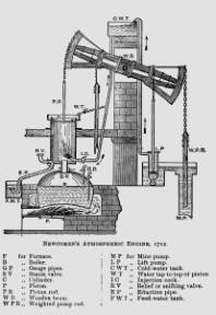
Diagram C ‑ Newcomen's 1712
atmospheric engine ‑ operation.
Referring to DIAGRAM 'C', the NEWCOMEN Engine
consisted of a boiler surmounted by the piston and cylinder, with the piston
rod being connected to a heavy wooden beam which rocked on trunnion bearings
situated on a specially strengthened outer wall of the engine house; at each
end of the beam were two 'arch‑heads' to which there were fixed link
chains. On each power stroke, atmospheric pressure forced the piston down to
pull on the 'in‑house' chain which in turn rocked the beam to lift the
pump‑rods attached to the 'out‑of-house' chain; when the power
stroke was spent the weight of the pump‑rods rocked the beam 'out‑ofhouse'
and carried the piston to the top of the cylinder again and then the cycle was
repeated.
Referring to the drawing, the method of operation in
detail was as follows: the Furnace F fired a 'haystack' boiler B to produce
steam at a pressure of about 5 psi. which flooded into the cylinder when the
piston was at the top of its stroke and the steam valve SV opened. When the
cylinder was filled with steam, the valve SV was closed and the water injection
cock IC was opened; this water condensed the stream in the cylinder to cause a
vacuum to be formed beneath the piston, which was then driven downwards by the
pressure of the atmosphere (14.7 psi.) to bring the beam 'in‑house' and,
hence, lift the pump rods which were connected to a pump bucket at the base of
the mine. When the piston had reached the bottom of its stroke any residual
water left in the cylinder was driven out via the eduction pipe EP to a
separate feed‑water tank, and any air in the system was released through
the 'snifter' or relief valve RV. This latter valve was so named by NEWCOMEN
because of
the curious noise that it made. By now the weight of the pump rods etc. was
sufficient to draw the piston to the top of the cylinder, and the beam was said
to be 'out‑of‑house'. Other apparatus shown in the drawing included
the lift pump, LP, to feed the cold water tank for injection and also to provide
a water seal on the top of the piston to prevent steam and vacuum losses.
Ancillary chain drives to operate the lift pump and a feed water pump were
placed in‑board of the arch‑heads and these were called 'little
arches'. At first all of the valves and cocks were operated manually and the
engine man had to go around opening and shutting them; firstly he would ensure
that the water seal on top of the piston was made, then he would open the steam
valve. When the beam came 'in‑house' after the steam valve had been shut,
and the injection valve opened, that injection valve would be shut and the
eduction valve opened to release the residual water He also had to try to
operate the try cocks on the gauge pipes on the boiler to ensure that water
levels were maintained inside the vessel. All of this was very labour intensive
and arduous and soon after its inception the NEWCOMEN engine was fitted with
automatic valve gear. The move towards automation came unexpectedly, so the
story goes. The popular theory is that an attendant, a boy name POTTER, tiring of the monotonous task
of operating all of the valves, connected them together in sequence with lines
of cord. In the manual form of operation the attendant had to be very wary in
case the piston hit the base of the cylinder, or allowed the piston to be drawn
out of the cylinder at the top of the stroke, allowing the beam to go 'out‑of‑house'
with disastrous results; with automatic operation, stops were fitted to prevent
either of the above mishaps and strong cords were fitted to operate the valves.
These cords etc. were gradually replaced with rods, catches and detents and in
1718 a Land Surveyor and engineer named BEIGHTON is thought to have formulated a coordinated
form of valve
gear when he erected a NEWCOMEN Engine at Oxclose. Incorporated with the valve
gear was another piece of equipment called the 'buoy' which ensured that
another power stroke was not made until the boiler had recovered sufficiently
to enable it to provide enough steam for the following cycle. Unfortunately
over a space of nearly three hundred years the stories of invention and
modification and their creators have become muddled; some credit HENRY
BEIGHTON with
the valve gear improvements, whilst other give the sole credit to NEWCOMEN and CALLEY;
the boy POTTER
has always
been credited with the invention of the 'Scoggan', or detent, but this is open
to discussion. Some details of the method of the operation of the valve gear
are shown in the diagrams on the next page which shows the steam admission gear
and the injection valve gear. With the atmospheric engine NEWCOMEN managed to hold a pressure of
6.4 psi.. continuously in the cylinder ‑ no mean feat at the time
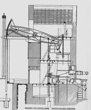
Fig. 6 ‑ The Newcomen atmospheric engine
built by Francis Thompson for Oakerthorpe Colliery in 1791. It was removed to
Pentrich Colliery in 1841 and worked, in total, for a period of 127 years.
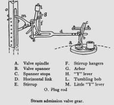
Early Valve‑gear Systems used on NEWCOMEN Engines
The Steam Admission Valve:
When NEWCOMEN engines were originally fitted with the
means for working automatically, the arrangements were constructed according to
the drawings depicted on the right. For the admission of steam, the valve at A
oscillated from side to side to close or uncover a port in the pipe from the
boiler to the cylinder; this was actuated as follows: As the Plug Rod O rose and fell, a pin moved
the little 'Y' lever M up and down to rock the arbour G which in turn imparted a motion to the 'Y'
Lever H
which had a weight at its extremity to enable it to go over centre. This allowed
the stirrup E to move horizontally and pull the 'spanner' up against one of the stops
at C. The
'spanner' was attached to a spindle which in turn was fixed to the admission
valve. This system allowed the position of the beam to determine the admission
of steam.
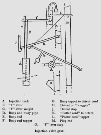
The Injection Valve:
This system also worked on the plug rod at M and, as it descended, it
depressed the end of the 'F' Lever C until it reached the closed position where it was
retained by the detent H. At this point the 'buoy' took over, for the steam valve having opened
and filled the cylinder as the engine went 'out‑of-house', the buoy
precluded another power stroke until the boiler had recovered. When the steam
dome on the boiler became re‑filled, the pressure inside allowed the buoy
to rise and release the detent rod and allow the 'F' Lever to fall by gravity
and so open the injection cock. The 'POTTER CORD' allowed manual over‑ride
as well as controlling the detent
Subsequent Historical Data
concerning the NEWCOMEN Engine.
Following the death of THOMAS SAVERY on the 15th May in 1715, his
patent rights were passed on to his wife, MARTHA, who by the good offices of JOHN
MERES, the
Secretary of the Worshipful Company of Apothecaries, was able to have them
invested in a Joint‑Stock Company which was known by the title of
"The Proprietors of the Invention for Raising Water by the Impellant Force
of Fire". The governing body of this organisation was known as the
"Committee of the Proprietors" and amongst others, THOMAS NEWCOMEN
was an important
member; most of the other personalities involved in this committee had
influence in the City of London. These Proprietors sought to contain the Patent
and licence its use to selected engineers and engine builders and thus preserve
a monopoly; to this end an advertisement appeared in the LONDON GAZETTE for the
11th/14th of August 1716 which gave notice that 'any person desirous to treat
with the Proprietors for such engines' should repair to a coffee‑house in
Birchin Lane to see one of the Proprietors, EDWARD ELLIOT, every Wednesday to discuss
terms.
Of course this monopoly exerted a stranglehold on the
industry in the same way that BOULTON & WATT managed to do later on in
the 18th Century and H. J. LAWSON and GEORGE B. SELDEN did to the motor industry at
the end of the 19h Century. However, as the Patent expired in 1733, the power
of the Proprietors was curtailed as the invention came into the public domain
and the payment of royalties ceased. Nevertheless the Proprietors did have a
good run for their money, for in the period between 1712 and 1733, some 110
engines had been erected at home and overseas and the NEWCOMEN system became an
established form of effective motive power.
Improvements to the
NEWCOMEN Engine:
It has been noted previously that although the
NEWCOMEN engine was, indeed, 'fit for purpose' it was inefficient in the use of
fuel and water and, therefore, there was a great need for improvement.
Notwithstanding that the invention was the 'wonder of the age' and that its
appearance in the 18th Century was akin to the Moon Landings in 1969 during the
20th Century, there was, as with the Moon Project, a hiatus following the lapse
of the Savery patent during which little or nothing was achieved by way of
advancement.
One of the main problems that had to be overcome was the
restriction on cylinder diameter occasioned by the use of brass for the
castings. In the early days of the NEWCOMEN engine, brass could be machined
more accurately than other materials but it restricted the size to diameters
below 36 ins. This persisted to the 1720s until ABRAHAM DARBY perfected the
casting of engine cylinders in iron at his COALBROOKDALE IRON WORKS. For a
period of forty years the COALBROOKDALE concern enjoyed their own monopoly of
cylinder casting and by 1761 they were able to produce cylinders as big as
74-1/2 ins, diameter by 120 ins, in length. The demand for these iron cylinders
started slowly but it soon accelerated and, with the appearance of the BOULTON
& WATT engine in the 1770s and 1780s, the demand for larger cylinders
weighing over 6 tons each outstripped the resources of the COALBROOKDALE firm.
It was left to JOHN SME TON, the builder of the Eddystone
Lighthouse, to effect real and lasting improvements to the NEWCOMEN engine.
Whereas earlier engineers had tended to work empirically, SMEATON introduced an element of
science into his modifications. The methods of empirical working did stultify
improvement and SMEA TON's work enhanced the performance of the atmospheric
engine. JOHN SMEATON formulated a system of measurement of the performance of engines which
he called the 'duty' this measurement was the amount of water in millions of
pounds (a.v.d.) that could be raised one foot high per bushel of coal (a bushel
weighing 84 lbs.). This standard enabled one engine to be compared to another
to ascertain relative efficiency. He selected some NEWCOMEN engines at work on Tyneside
for comparison and he found that loadings and overall performance varied
greatly ‑ a well loaded engine from point of view of piston pressure did
not necessarily point to the best duty achieved and he found in his studies
that a 60 ins, machine performed better than one having a cylinder diameter of
75 ins.! The former engine achieved some 3 h.p. better than the latter when translated
into horse‑power figures. The reason for this discrepancy lay in the
degree of accuracy of manufacture of the components, and SMEATON discovered that some of the
cylinders allowed the piston to be slack in the bore, whilst others were tight;
valve gear did not admit the right quantity of steam to work effectively and so
on. Other factors were present such as too short a stroke, boiler grates
pitched too low to provide the correct heat values to be extracted from the fuel whilst too much water accumulated
on top of the piston to cause excessive cooling. SMEATON was associated with another
famous ironworks of the time which was the first such enterprise in Scotland ‑
the CARRON IRONWORKS ‑ noted for their 'potbellied' coke stoves today.
This foundry went into production in 1760 and SMEATON designed the plant there; one
of the tools that he introduced was an accurate cylinder boring mill which
could produce a truly circular bore. The entrance of the CARRON IRONWORKS into
the fray ended the COALBROOKDALE monopoly.
Amongst the improvements that SMEATON effected were his special form
of piston, shown in Diagram 'D', an improvement on the NEWCOMEN type which had
consisted of a flat plate with a broad strip of leather screwed to it and
turned up at the sides some two or three inches in the cylinder. This piston
gave considerable trouble owing to its irregular fit which caused leakage and
the fact that the leather was often cut up being then worse than useless. SMEATON
applied
scientific data to the admission of steam and the amount of injection water
needed to cause condensation in the cylinder with the wooden underside of his
piston preventing waste in this direction. He introduced a feed‑water
heater system and increased the flexibility of the working strokes by means of
regulation of steam volumes rather than shortening the stroke and replacing the
'buoy' system with a 'cataract' which allowed a water trough and cup system to
vary the weight operating the 'F' Lever which controlled the injection cock.
When the engine worked at maximum power the cataract was put out of use, but as
loads decreased due to there being less water in the mine, the cataract could
be linked to the cycle to regulate the number of strokes per minute by
adjusting the amount of water held in the cup to achieve a variable weight
effect. SMEA TON adopted a hemispherical cylinder bottom and a laminated timber beam with
its trunnions set at its mid‑point instead of below as had been the norm
when timber baulk beams were used.
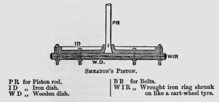
Diagram D.
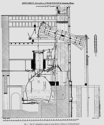
All of SMEATON's improvements were embodied in his 52 ins,
engine erected at the LONG BENTON COLLIERY, Northumberland in 1722 (Fig. 7).
This engine worked at 12-1/2 strokes per minute on a mean effective pressure of
7.5 psi. to return a duty of 9.45 millions, whereas the best recorded duty
figure that he had found on Tyneside was only 7.44 millions. SMEATON then built a number of other
engines that included his improvements and these were located at Chacewater in
Cornwall where he built a 72 ins, machine in 1775, at Kronstadt in Imperial
Russia where a 66 ins, engine was supplied for emptying docks, and several
others that were used variously in mines and waterworks.
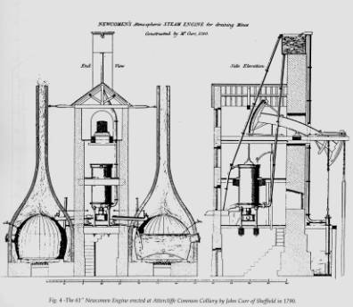
Another improver of the atmospheric engine was one JOHN
CURR of
Sheffield who decided to locate the boilers remotely to obviate the need to
mount the cylinder over the boiler steam‑dome. JOHN CURR wrote a book
entitled "The Coal Viewer & Engine Builder's Companion" which was
published in 1797 and following this he erected a 61 ins, engine at Attercliffe
Common Colliery in 1790, (Fig. 4), which embodied his principles. For this
plant he used two boilers located in outhouses alongside the engine-house and
these were connected together by means of a common steam pipe which joined in a
chest beneath the cylinder; this configuration enabled CURR to build a more compact engine
house which provided a greater degree of support for the cylinder and its
ancillary equipment. Previously, when the cylinder was mounted atop the boiler,
there were fractures in steam pipes and failures in the jointing because the
cylinder, not being adequately supported, tended to flex excessively at each
stroke and cause such problems. Another improvement made by CURR was to increase the elevation
of the injection water cistern, placing it on an extended wall of the house to
be situated well above the roof. The stroke of the Attercliffe Common Colliery
engine was 81/2 ft. and it made 12 strokes per minute to return a duty of 9.38
millions
Other modifications to the original NEWCOMEN style of engine are noteworthy and: they include the introduction of the ‘pickle-pot’ condenser, the replacement of the link chain by the pitch–chain (like a bicycle chain with plates and rollers) on the arch heads and the fitment of drop‑valves and and sliding valves in place of the plug cocks. The 'pickle‑pot' condenser was placed below the cylinder and it was in direct communication with it through a large diameter pipe; cold water was injected into the 'pickle‑pot' instead of into the cylinder and later on in the cycle the incoming steam blew the condensate and any air present out via a non‑return valve that was loaded at about 2 p.s.i. This method was not too efficient though it did possess the advantage that when the steam was admitted into the cylinder it was not exposed to so great a volume of condensate as hitherto. Messrs. BOULTON & WATT always considered the 'pickle‑pot' condenser to be an infringement of their 1769 Patent, though they are never recorded as having resorted to litigation to suppress its use. However, many features of the improved engine as built by BOULTON & WATT were incorporated in atmospheric engines erected after the lapse of the 1769 Patent in 1800, and these included the use of the separate condenser, the fitting of the WATT water cataract governor together with drop and sliding valves and the replacement of the wooden beams with cast‑iron units having the WATT parallel motion at the piston rod end.
Notes on Important NEWCOMEN Engines and those Existing Today
One of the most famous NEWCOMEN Engines to be
documented was that erected at the South Liberty Colliery which was owned by
the ASHTON VALE IRONWORKS of Bedminster in Bristol. This engine, which is
depicted in Fig. 3, was the last atmospheric unit to operate in the West of
England and it was one of the longest lived, working from about 1750 until 1900
when, unfortunately, it was scrapped. Luckily it was extensively documented by BRYAN
DONKIN M.I.C.E.. in the journal
"ENGINEERING" for their issue of the 25th October 1895. In the
article, which was derived from fieldwork carried out by H.W. PEARSON M.Inst. Mech. E. in the
May of that year, there were several supporting photographs of the old engine
together with drawings (Fig. 3) and, interestingly, an Indicator diagram.
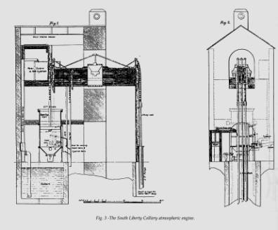
The South Liberty Engine was seen in the photographs
to have retained its massive, wooden, laminated beam made on the SMEATON
pattern and which measured 24 ft ins length by about 4 ft.
in depth as well as having pitch‑chains on the arch-heads
instead of link‑chains; the cylinder dimension was 66 ins, and it had a
stroke of 6 ft. This cylinder was designed with a conical bottom to gain ease
of condensate drainage in a similar manner to SMEATON's hemispherical shape,
and it weighed 6 tons. The Indicator Diagram, alluded to previously, recorded a
boiler pressure of 2.3 p.s.i. and a mean effective pressure of 9.5 p.s.i. at a
rate of 10 strokes per minute ‑ this gave a Horse Power rating of 52.72.
When one considers the weight of the engine in total, the boiler, the pitwork
and the pumps, the horse power per ton figure is minimal, but nevertheless,
these engines did do their work well considering the time at which they were
made. Over its 150 years of use, the South Liberty Engine worked for about 5
hours per day, for 6 days a week. The engine‑man who was driving it in
1895 had driven it since he was a boy, his father and grand‑father having
driven it before him.
Another important machine was the 72 ins. Chacewater
engine erected by JOHN SMEATON in 1775 which has been mentioned previously. It was
one of the most powerful NEWCOMEN prime movers that had been made up to that
time and it was the largest such engine to work in Cornwall with a stroke of 9
ft. and going at 9 strokes per minute it developed 76 h.p. It was fitted with
SMEATON's laminated wooden beam which measured 27 ft. 4 ins, in length, by 2
ft. wide and 6 ft. 2 ins, deep at its centre; this beam was made up from twenty
pieces of fir measuring 12 ins. x 6 ins, in section and all bolted together.
The Chacewater engine worked three 16-1/4 ins, pumps in series which drew water
from a depth of 306 ft. to adit
level. Apparently it did not last long as an atmospheric engine for in 1778 it
was re‑built by JAMES WATT being fitted with a new 63 ins, cylinder which was
cast by WILKINSON; the original cylinder was retained and was used as an outer casing for
the new one.
From research that was conducted during the latter
half of the 20th Century, it appears that 1454 NEWCOMEN or atmospheric engines
were constructed world‑wide by the end of the 18th Century just prior to
the expiry of the BOULTON & WATT Patent in 1800. If one counts the two
rotative units that are preserved in Scotland and in the U.S.A., only seven
survive to the present day.