The Steam Engine
of
Thomas
Newcomen
L. T. C Rolt & J. S.
Allen
Moorland Publishing
Company
Hartington
Science History Publications/
USA
New York ‑-1977
COPYRIGHT NOTICE
All rights reserved. No
part of this publication may be reproduced, stored in a retrieval system, or
transmitted, in any form or by any means, electronic, mechanical, photocopying,
recording or otherwise, without the prior permission of Moorland Publishing
Company.
Published in Great
Britain by
Moorland Publishing
Company,
The Market Place,
Hartington,
Buxton, Derbys, SK17 OAL
First published in the
United States by
Science History Publications/USA
a division of
Neale Watson Academic
Publications, Inc.
156 Fifth Avenue, New
York 10010
Printed in Great
Britain by
Wood Mitchell & Co
Ltd, Stoke on Trent.
Ed. The following excerpts from Chapter 5,
Pages 89 – 110 give detail not found in other publications. J.McV Oct
2006

Fig.
17

Fig.
21
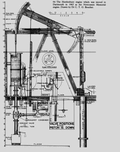
Fig.
94 The Hawkesbury Engine
CHAPTER 5
Technical Developments 1712-33
In
order to present the story of Newcomen and his engine as clearly as possible a great
deal of technical detail has been omitted from the preceding chapters. Such
detail is essential, however, to any assessment of Newcomen's achievement
because so many conflicting statements have been made as to how, and by whom,
certain features of the engine were developed. Quite apart from the need to pay
Newcomen his due, the story of how men, who were quite ignorant of the nature
of steam or the laws of thermodynamics, groped their way to success by sheer
practical ingenuity and tenacity of purpose is a fascinating one.
To
appreciate to the full the achievement of Newcomen and his associates, the
reader must use his imagination, forget his twentieth‑century background
and try to think himself back into those far‑off days. Such an
imaginative effort is essential if the error of hindsight is to be avoided,
because the solutions of many of the problems with which Newcomen grappled now
seem so obvious as to be self‑evident even to those who are not
technically minded. Even some of Newcomen's contemporaries and immediate
successors made this same mistake, so fatally easy to be wise after the event.
The most brilliant inventions are those which seem obvious once they have been
explained or demonstrated. 'Why, I could have thought of that', we say with a feeling
of envy and mortification, and it is clear from their writings that both
Desaguliers and Triewald reacted in this way, convincing themselves that they
could have done better than Newcomen had they chosen to bend their minds to his
problems.
Next
to the principle of injecting water into the cylinder to create a vacuum, the
most significant feature of the Newcomen engine was the valve gear, or 'working
gear' as it was called, which made it self‑acting. No early writer awards
Newcomen any credit for this valve gear and the only legend about his engine
that deserves to be called popular would have us believe that the valves were
worked by hand until a boy, tiring of this monotonous task, connected their
handles by strings to the beam. There may be a grain of misunderstood truth in
this legend as we shall see presently.
Farey, in his Treatise on the Steam
Engine, summarizes the
evolution of the valve gear as follows:
At
first the valves were opened and shut by hand, and required the most exact and unremitting
care of the attendant, to perform those operations at the precise moment; the
least neglect or inadvertence might be ruinous to the machine, by beating out
the bottom of the cylinder, or allowing the piston to be wholly drawn out of
it. Stops were contrived to prevent both of these accidents; then strings were
used, to connect the handles of the cocks with the lever [ie the balance beam]
so that they should be turned whenever it reached certain positions. These
strings were gradually changed and improved, into detents and catches of
different shapes: till at last, in 1718, Mr. Beighton, a very ingenious and
well‑informed engineer, simplified the whole of these subordinate
movements, and brought the machine into the form in which it has continued, to
the present day, without any material change.
Stuart, in his History of the Steam
Engine, goes further
than this. His plate entitled 'Newcomer's Engine' depicts an engine with hand‑operated
valves, while the next figure showing an engine with self‑acting valve
gear is headed 'Beighton's Engine'. His accompanying text reads:
The
mechanism for opening and shutting the cocks also remained perplexed by catches
and strings, until Mr. Henry Beighton, an engineer extensively employed in the
construclion of mining machinery, erected an engine at Newcastle‑on‑Tyne
in 1718, in which all these "cock‑boys" and complications of
cords were superseded by a rod suspended from the beam, which operated on a
mechanism invented by him called hand‑gear: a contrivance, with some slight
mod)fications, employed in engines of the present day.
Although
it is not possible to back the statement with positive proof, it is safe to say
that the hand‑operated valves referred to by Farey and illustrated by
Stuart belong to the experimental period before 1712. From that date forward
Newcomen's engine had the self‑acting valve gear evolved by him and his
assistant Calley and differing only in one important respect from that which
was later standardized and used with only minor variations down to the end of
the eighteenth century. This one
important difference accounts for the references to catches and strings as
well as for the legends about the ingenious 'cock boy'. The fact that these
references and legends are woefully misleading is due to a failure to
understand the difficulties— some of them due to lack of knowledge and
experience—encountered by Newcomen at the outset and the way he met them.
Before these difficulties and Newcomen's solutions to them can be understood,
it is essential to consider two things: the adequacy of the boilers used on
Newcomen's first engines and this method of calculating the work these engines
could perform.
It
will be recalled that when Nicholas Ridley proposed to erect a second engine at
his Byker colliery with a 33in cylinder the inventors, presumably Newcomen and
Calley, refused to undertake the project on the grounds that so large a
cylinder could not be supplied with sufficient steam. Commenting on this
refusal, Triewald writes:
The
cause of this conclusion was the false principles concerning the steam which
the inventors harboured in their minds according to which the steam rises or is
generated by the boiling water in proportion to the quantity of water in the
boiler. In consequence their boilers were made very high, as demonstrated by
the Stafford [Dudley Castle] engine, the boiler of which is higher than its
width. It is thus evident that the inventors do not know that the boiler must
be given a suitable shape. Neither did they know that the flames should be
allowed to play all around the side of the boiler as well as on the bottom....
Although
Triewald was a conceited young man and apt to be wise after the event, there is
no doubt that in this case his criticism was valid. It may seem obvious to us
that the steam generating capacity of a boiler depends on its heating surface
but this was by no means obvious in 1712. To suppose that it was only necessary
to increase the quantity of boiling water in order to obtain a proportionate
increase in the volume of steam produced from it was then a perfectly
understandable
error. Moreover, although Triewald appreciated the need to increase the heating
surface, this conclusion was purely empirical and boilers continued to be built
on an empirical basis for more than sixty years. The first Watt engines were
under-boilered and this defect led Watt to work out, for the first time, a
desirable ratio between boiler heating surface and cylinder volume. He
specified four square feet of heating surface per cubic foot of cylinder
volume.
The type of boiler used by Newcomen consisted of a
cylindrical copper vessel with a concave bottom directly above the furnace.
This was surmounted by a hemispherical steam dome of lead. The diameter of this
dome was greater than that of the copper cylinder below, the upper portion of
the latter being flanged outwards at right‑angles and then turned upwards
again in order to form a circumferential seam with the lead dome. It thus
resembled a haystack in crosssection and it became know as a ' haystack'
or 'flange' boiler, sometimes also called a 'balloon' or 'beehive' boiler. This
was certainly the type of boiler supplied initially to the Whitehaven engine,
although Spedding stated that it was the first of its type that Newcomen and
Calley ever had and they did not approve of them as much as those without
flanges. The brickwork enclosing the furnace was carried upwards round the
boiler and sealed against the lead dome plates. This arrangement left an
annular space beneath the dome and through this the hot gases from the furnace
circulated before passing up the chimney stack. The proportions of the boiler
were such that at working level there was but little depth of water upon the
copper 'roof' of the annular flue and this made it vulnerable in the event of
mismanagement. Although at an early date, high and low level try‑cocks
were provided so that the water level could be checked, attendants all too
frequently allowed the level to fall low with the result that the copper 'roof'
overheated and this led to the failure of the copper‑lead seam at its
circumference. The Austhorpe engine is said to have burned out four boilers in
this way in as many years. The first boiler at Whitehaven suffered the same
fate and had to be repaired first with lead and copper patches and then lined
all round with lead held on with lead nails. Although the eventual substitution
of wrought‑iron plates for copper and lead boiler less liable to suffer
from overheating, what was known as the 'tun' boiler came to be favoured by
later builders. Instead of the angular construction of the Newcomen 'haystack',
the lower portion of the tun boiler was cylindrical, tapering down from the
diameter of the steam dome to that of the concave bottom plate immediately
above the furnace. This entailed a certain loss of heating surface, but this
sacrifice was offset by altering the proportions of the boiler and its furnace
and flues. The second boiler at Whitehaven was made from iron plates with a
lead top and supplied by Stonier Parrott in 1717. It was reported as being
broader at the bottom and narrower at the top than the first boiler. This was
to give trouble in service at the junction of the iron and lead and the iron
corroded externally in this area. As early as March 1717 Mr Calley had
commented that 'he approved very well of iron boilers' indicating their use
elsewhere prior to this time.
So ingrained in us is the importance of a
large heating surface that modern diagrammatic representations of the early Newcomen
engine almost invariably depict a haystack boiler of a diameter exceeding its
height. By contrast, Barney's engraving of the Dudley Castle engine shows a
brick furnace and boiler casing of considerable height in proportion to its
diameter. It is particularly interesting to note that Barney shows the firehole
door in an impossible position above an arched access doorway to the ash-pit so
high that the fireman depicted in the foreground could walk through it without
stooping. Without the aid of a stepladder he would have had to be a gymnast to
put coal on the fire and would certainly need the 'little Bench with a Bass to
rest when they are weary' which, according to Barney's key, was thoughtfully
provided. This odd aspect of the drawing may be due to Barney's method of
showing the ash hole and engine‑water pump below the engine‑house
floor. The engine man is standing at the firing‑floor level but this part
of the drawing is moved forward to permit the lower level to be seen. Barney's
accompanying key tells us that the boiler was 6ft 1 in high but that the
diameter of the bottom plate was only 4ft 4in. Barney also gives the capacity
of the boiler as 'near 13 Hogsheads', this being the equivalent of
approximately 680 imperial
gallons. Having regard to the srr.all heating surface available, this was an
immense volume oi water and Barney’s figures thus corroborate Triewaid's
criticism of the Oucley Castle engine. It is clear that: as he says,
Newcormen did believe at this time that if he increased the
volume of water in a boiler its OUtpilt of
steam would increase proportionately . The full significance of this will
appear presently.
It is also interesting to note that the
von Schonstrom drawings of the Konigsberg engine show a plain boiler without
flanges.
The valve or 'regulator' that controlled
the admission of steam from the boiler to the bottom of the working cylinder
was mounted in the top of the steam dome and it resembled the type of valve
used by Savery on his later engines. It consisted of a fan‑shaped brass
plate which, moving to and fro horizontally, alternately covered and un‑covered
a steam port formed in a second brass plate rivetted into the top of the
boiler. On some engines the moving plate was held to its port face by a flat
steel spring, bridging the steam orifice below and bearing against a boss
formed on the lower surface of the plate. From the fixed brass plate in the top
of the boiler the steam pipe extended upwards to meet in a butt joint a pipe of
the same diameter passing through the centre of the cylinder bottom. This butt
joint was wrapped, first with canvas covered in white lead and oil, then with
sheet lead and finally bound tightly with cord. This primitive method of
jointing persisted for years despite frequent failures caused by movement of
the cylinder while the engine was working under load.
The vertical spindle of the moving sector
valve was tapered like the barrel of a plug cock where it passed through the
fixed brass plate in the boiler top and it was ground into a taper seating
formed in the latter in order to keep it steam‑tight. To the squared end
of this spindle a spanner was attached which could be worked to and fro by a
linkage arranged as follows. First there was pin‑jointed to the spanner a
horizontal link called the 'stirrup' because it was so shaped at its opposite
end. The forked ends of this slirrup were supported by two vertical links,
harlging loosely from a horizontal arbor which they shared with two levers
called the i' lever and the 'little Y'. Both were fixed at their common axis.
The Y lever was in the shape of that letter inverted and it carried a weight or
tumbling bob on its upper end. As it rocked on its arbor and the weight was
thrown over centre, its two lower arms alternately struck the crosspiece of the
stirrup and thus opened and closed the valve, the action of the weight ensuring
rapid and positive action. The plug rod which hung from the beam imparted this
rocking motion to the arbor by means of the little Y lever. Pegs in the plug
rod alternately raised and depressed the arms of this little Y as the rod rose
and fell. The valve spanner itself was provided with positive stops and there
were two methods of adjusting the motion. The pegs in the plug rod could be
moved into alternative holes, while a series of holes in the arm of the stirrup
enabled the pin‑joint by which it moved the spanner to be adjusted
similarly. This type of steam valve and its operating linkage persisted almost
unchanged for many years withonly detail refinements and it is safe to credit
its inception, not to Henry Beighton, but to Newcomen and Calley. The design of
the valve itself may have been derived from Savery, but the ingenious self‑acting
gear was entirely original.
 The admission of
injection water to the cylinder was controlled by a simple plug cock. To the
designer of the steam admission gear it would have been a simple matter to
develop a similar linkage to actuate this cock from the plug rod, but Newcomen
did not do this for two closely associated reasons: the limited steam
generating capacity of his boiler and the excessive load he imposed on the
engine.
The admission of
injection water to the cylinder was controlled by a simple plug cock. To the
designer of the steam admission gear it would have been a simple matter to
develop a similar linkage to actuate this cock from the plug rod, but Newcomen
did not do this for two closely associated reasons: the limited steam
generating capacity of his boiler and the excessive load he imposed on the
engine.
Desaguliers,
who was doubtless supplied with the information by Henry Beighton, has this to
say about Newcomen's method of estimating the power of his engines: Mr
Newcomen's Way of finding it was this: From the diameter [of the cylinder]
squar'd he cut off the last Figure, calling the Figure on the left Hand long
Hundreds, and writing a Cypher on the right Hand, call'd the Number on that
Side, Pounds; and this he reckon'd pretty exact as a Mean, or rather when the
Barometer stood at 30 and the Air was heavy. N.B. This makes between 11 and 12
pounds upon every superficial round Inch. Then he allow'd between 1/3 and 14
Part for what is lost in the Friction of the several Parts and for Accidents:
and th~is will agree pretty well with the work at Griff Engine, there being
lifted at every stroke between 2/3 and 3/4 of the weight of the atmospherical
Column pressing on the Piston.
This
works out at a mean effective pressure of 9-1/2 1b/in2, an optimistic figure
bearing in mind that the atmospheric pressure employed could not exceed 14
lb/in2. Seventy years later the cautious Watt, although he was using steam at a
pressure slightly exceeding that of the atmosphere, allowed a mean effective
pressure of only 5 lb/in2 on his first rotative engines. The figure of 9-1/2
lb/in2 adopted by Newcomen meant that his first engines were so loaded that
their working depended on the creation of a high degree of vacuum below the
piston.

When
the engine had made its power stroke, or 'come into the house' to use the
current engineman's expression, the piston was returned to the top of the
cylinder by the weight of the descending pump rods at the other end of the
beam. So far from being asssisted in this motion by the incoming steam, the
pressure of the steam above atmosphere being negligible, the piston in its
ascent actually helped to draw the steam from the boiler into the cylinders.
The steam-generating capacity of the first boilers was so inadequate that the
sudden extraction of so great a volume of steam might literally have the effect
of sending the boiler 'off the boil'. If, therefore, water was immediately
injected into the steamfilled cylinder so that the engine made another
power stroke, the piston would once again be returned by the pump rods but
little or no steam would follow it because the boiler had not had time to
recoup. This, of course, would bring the engine to rest because in the absence
of steam no vacuum could be created. Faced with this problem Newcomen decided that the solution was to
regulate the working capacity of the engine in accordance with the steaming
capacity of the boiler.
This
solution took the form of a contrivance called a buoy. This was a small buoy
floating upon the surface of the water in the boiler and enclosed in a vertical
tube—the 'buoy pipe'—which protruded through the dome of the boiler
and carried within it a rod attached to the buoy. By means of this rod the buoy
controlled the opening of the injection cock in the following way. This cock
carried a shaped lever which became known as the 'F' because of its shape. With
the cock in the closed position, this F‑lever lay at an angle of about
30°to the horizontal, with its foot nearest to the plug rod and the letter
inclining upwards therefrom with the two short arms pointing downwards. The
shorter of these two arms was pierced with the square hole fitting over the
spindle of the injection cock, while the longer carried a weight at its
extremity. A short prolongation of the lever beyond the junction of this upper
arm engaged with a pivoted catch or detent lever known as the 'scoggan'. This
detent retained the lever in its closed position against the reaction of the weighted
arm which would otherwise fall and cause the injection cock to open.
Towards
the end of the engine's power stroke a peg on the descending plug rod depressed
the foot of the F‑lever until it reached the closed position where it was
retained by the detent. It was at this point in the cycle that the buoy came
into play. The steam admission valve having opened and refilled the cylinder
with steam as the piston 'went out of the house', the buoy ensured that another
power stroke was not made until the boiler had recouped itself sufficiently to
cope with the next demand for steam which must follow the power stroke
immediately. When the dome of the boiler had again filled with steam, the
slight pressure so created was aufficient to cause the buoy to rise in its
pipe, whereupon the vertical rod attached to it raised the detent lever, thus
enabling the F lever to fall by the action of its weight and so open the
injection cock. It is important to note that in devising this ingenious cycle
of operations Newcomen took it for granted that the steam demand of the
cylinder would temporarily exhaust the boiler and so allow the buoy to fall.
For if the buoy did not fall it would prevent the detent lever from returning
to position in order to retain the F lever when the descending plug rod again
restored the latter to the closed position.
It
follows logically that so long as the engine was controlled by the buoy its
action would be extremely slow. Whereas the word 'engine' to us implies
continuous motion, on the first Newcomen’s each return of the pump rods would be followed by a
prolonged pause while the boiler regained the necessary strength to perpetuate
the cycle of operations. It seems clear, however, that. partly as a result of
this extremely slow action, Newcomen did achieve a high degree of vacuum in his
cylinder which enahled the engine to work a load as high as 9 lb'in2 on the
piston. This compensated to some extent for the very slow rate of pumping.
Notwithstanding
the fact that instead of positive evidence we have a fog of confusing and
contradictory statements; the subsequent development of the engine can be
deduced with the assurance that, although it is necessarily conjectural, it
cannot be far from the truth. One explanation of the legend of the ingenious
boy with the piece of string is that it arose as a result of a
misunderstanding of the fact that
the ‘buoy' used by Newcomen was
not of the two‑legged species. Although such a misunderstanding may have
added to the confusion, it seems far more probable that such a boy did exist
but that those who mentioned him did not understand what he was set to do or
what it was that he achieved with his piece of string.
It
is obvious that, as soon as a Newcomen engine was provided with a boiler of adequate
steam‑generating capacity, it became no longer necessary for the boiler
to govern the working rate. Moreover, the old control gear could no longer
operate because the buoy would keep the detent or scoggan permanently raised so
that there would be nothing to retain the injection cock in the closed position
during steam admission. When this first occurred there was only one way in
which the engine concerned could be kept at work. This was by putting the buoy
out of action by wedging its rod in the pipe and then lifting the detent by
hand each time the piston reached the top of its stroke. The engine would then
work at a much faster rate provided the boiler could continue to maintain the
steam supply. I~o perform this monotonous operation, a two‑legged boy was
pressed into service instead of Newcomen's similarly named device. Standing
close beside the rising and falling plug rod, it would not take this boy long
to realise that the plug rod could very easily be made to do his repetitive job
for him. A suitably positioned nail in the plug rod and a length of cord from
the nail to the detent lever were all that was necessary. How delighted he must
have been with his crude but effective improvisation as each time the plug rod
neared the top of its stroke the cord tautened, raised the cletent and so
allowed the injection cock to open !
John
O'Kelly tells us of the boy's invention:
At
the beginning, they only made 6 to 8 and 10 strokes per minute and it was as a
result of the invention of a youth who watched over the machine rhat they
managed 15 and 16 strokes in the same period of time. This boy was called
ilumphrey Potter, but this invention made the machine very complicated.
Young
Humphrey Potter was most probably the brother of Isaac and John who were the sons
of Stephen Potter, brother to Humprey, Sen, and clearly a family trio who had a
tremendous influence on the introduction and development of the engine.
Desaguliers
however gives a most muddled account of the affair as follows:
They
used to work with a buoy in the cylinder, enclosed in a pipe: which buoy rose
when the steam was strong, and opened the injection and made a stroke: thereby
they were only able from this imperfect mechanism to make six, or eight, or ten
strokes in a minute; till a boy named Humphry Potter, who attended the engine,
added what he called a scoggan ‑ a catch, that the beam (or lever) always
opened; and then it would go fifteen or sixteen strokes in a minute.
It
is evident from this that the worthy scientist totally failed to grasp both the
object and the working principle of Newcomen's buoy gear. He begins by placing
the buoy in the cylinder, then blames the 'imperfect mechanism' for the fact
that the engine worked so slowly and finally credits the boy Potter with the
introduction of the detent lever or scoggan; all this to the infinite
bemusement of subsequent writers.
A
good example of the way in which nonsense begets nonsense appeared long
afterwards in the Mechanic's Magazine and was quoted by Stuart. Accepting
Desaguliers's account, the writer announced that the word scoggan was derived
from a north Yorkshire verb 'to scog', meaning to skulk or idle and that it was
obviously applied to the detent lever because it enabled its youthful inventor
to idle instead of attending to his monotonous job. In fact the word is of
Cornish origin and was doubtless first applied to the detent lever by Newcomen
or his associates during the course of pre‑1712 experiments in Cornwall.
The term is still applied in Cornwall to the Cornish engine valve gear, but it
will soon become an archaism now that this ultimate development of the
non-rotative beam engine has become a museum piece like its predecessors.
It
should be emphasized at this point that in designing his sorely misunderstood
method of operating his injection cock. Newcomen was the first to adopt the
principle of opening the valve by the fall of a weight and closing it against
gravity, a principle which has proved as long‑lived as the word scoggan,
since it persisted through the Watt era down to the last Cornish engine to be
built.
The
acceleration of the engine from a mere six strokes a minute to twelve of
fifteen strokes by the use of a more efficient boiler and the substitution of
the 'Potter cord' for the buoy to regulate the opening of the injection valve
was not achieved without loss in another direction. The faster rate of working
allowed less time for the cylinder alternately to gain and lose its heat with
the result that the degree of vacuum achieved below the piston was reduced. The
mean effective pressure of 9-1/2 lb/in2 originally adopted by Newcomen was
reduced to 7 lb/in2 or in other words half atmospheric pressure, to counteract
this loss, but it was immediately found that the less heavily loaded engine
working at the faster rate pumped more water per hour than it did before. Nor
was any more fuel consumed in proportion to the work done because the more
efficient boiler wasted less of the heat generated by the furnace.
If
contemporary engravings are to be relied upon, it would appear that the
earliest Newcomen engines were soon fitted with a refined version of the
'Potter cord' but that the buoy gear was retained. Beighton (1717), Barney
(1719), and, most surprisingly, Triewald's engraving of the Dannemora engine
(1734) all show both. No doubt when the boiler was steaming badly and could no
longer sustain the rate of working imposed by the Potter cord, it was
disconnected so that the buoy could take control. Meanwhile, however, the
provision of more adequate boilers was accompanied by the rapid accumulation of
experience among the men concerned with the erection and management of the
engines with the effect that the time soon came when it was felt that the buoy
gear could be safely discarded. By far the most likely explanation of the claim
that it was Beighton who "invented' the self‑acting valve gear in
1718 is that it was he who first took this step by dispensing with both the
buoy gear and the Potter cord on the engine which he erected at Oxclose
Colliery, Washington Fell. This would also explain the statement that until
this time the engine had remained 'perplexed by catches and strings'.
Beighton
is also said to have been the first to fit a weighted safety valve, or 'puppet
clack' as it was called, on the boiler of this engine at the suggestion of
Desaguliers. It lifted at a pressure of 12 lblin2. This sounds logical since
the elimination of the buoy would make a safety valve the more necessary, but
the fact remains that a weight safety valve features in Beighton's engraving of 1717 along with the buoy and
the Potter cord.
Stuart's
engraving of what he calls 'Beighton's Hand‑gear' shows a very simple
method of working the injection cock by means of two toothed sectors engaging
in each other at rightangles, the driving sector being mounted on the
horizontal axis of a lever which was alternately moved up and down by two pegs
in the plug rod. One of the early engravings featuring a gear similar to this
is that showing the engine at Passy (1726) which illustrates the French account
of that engine. If this was Beighton's gear, it was soon discarded in favour of
a return to the weighted lever released by a detent. Desaguliers describes and
illustrates the toothed sector method of opening the injection cock, but also
illustrates the weighted lever and detent, which he says is 'more used, and I
think a great deal better; because it moves with a Jerk, which is the best way
to overcome Friction'. The method by which this lever turned the cock might
vary and, instead of the Potter cord, the detent was henceforth tripped by a
striker on the plug rod, but the principle of opening by falling weight became
firmly established. Experience has shown that the more rapidly and positively
the injection cock could be opened, the better the result and it was for this
reason that the simple gear credited to Beighton failed to supplant the
weighted lever and detent first developed by Newcomen.
It
must be emphasised that early pictures of Newcomen engines are not an
infallible guide to chronological development. Artists either failed to
understand the principle of the valve gear and drew it indistinctly or
inaccurately, or else they copied their predecessor's work. Thus the Sutton
Nicholls engraving of what purports to be the York Buildings engine (1725)
shows the buoy gear only, which is certainly incorrect, while it seems most
unlikely that the Dannemora engine would have had the buoy gear unless it was
that Triewald doubted the ability of his boiler to supply so large a cylinder.
Such vagaries become excusable when we realise that with the sole exception of
clock‑work, no other self‑acting mechanism existed in those days.
Besides
the alternative admission of steam and injection water to the cylinder,
provision had to be made for the exhaustion from the cylinder of the hot
condensate and of any air brought in by the steam. When steam was first
admitted, the hot water, which had accumulated in the cylinder bottom during
the previous stroke, was expelled down a pipe into a hot well. A leather non‑return
valve at the foot of this eduction pipe prevented the water being drawn back up
the pipe when a vacuum was created in the cylinder. In the earliest engines the
hot well was at ash‑pit level, but later it was located above the boiler
steam dome so that the hot water it contained could be fed by gravity into the
boiler. Beighton is said to have been responsible for this innovation. This
first form of feed water heating brought about a sign)ficant saving in fuel.
Apparently
Newcomen did not at first appreciate that a certain amount of air would be
carried into the cylinder with the steam and he was accordingly mystified by
the fact that his engine would gradually lose power until it finally stopped,
air having accumulated to such an extent that an effective vacuum could no
longer be created. When the cause of this malady, which became known to
enginemen as 'wind‑logging', was recognized, Newcomen cured it by fitting
a small outlet pipe to the lower part of the cylinder through which the
incoming steam could expel any air. Like the eduction pipe, and for the same
reason, it was fitted with a non‑return valve. Because of the noise it
made, this air outlet pipe became known as the sniffing valve, 'sniff' being
then the equivalent of our'sniff'. The pipe was led into a small tank of water
which Barney calls a 'sniffing bason'. There any steam which passed was
condensed while the air bubbled through it. The overflow from this tank, led
either to the hot well or directly to the boiler.
A
cistern, mounted a little below the axis of the beam in order to provide a
head, supplied the water for injection. It was replenished by a small pump
worked, like the plug rod which operated the valve gear, by a small auxilliary
arch‑head set closer to the axis of the beam than the main archheads
so that the stroke was reduced. In Beighton's engraving the arch‑head for
this pump is shown outside the house near the pump end of the beam. Barney's
engraving, on the other hand, shows the pump in the engine house and driven
from the end of the plug rod. The pumps used for this purpose were usually of
the type known as
'jack‑head'. They
were of the common lifting type, but the top of the working barrel was closed,
the bucket rod passing through a leather‑packed gland in the cover. As
the bucket ascended, the water above it was forced up a pipe which branched
from the top of the working barrel. If Barney's drawing is correct, however,
the Dudley Castle engine was fitted with a plunger force pump of the type
introduced by Morland. This pumped on the down-stroke and to cope with this the
plug rod is shown coupled to the beam by two opposed chains anchored to the
midpoint of the arch‑head. Such an arrangement cannot have worked satisfactorily
and a jack‑head pump driven by a second auxiliary arch‑head on the
pump end of the beam became the rule.
The
water seal on the top of the piston was replenished by a branch taken from the
injectionwater supply pipe. Barney's drawing omits this supply pipe and
shows both the water seal and injection pipes branching from the pump delivery
pipe which delivers into the top of the cistern, an arrangement that could not
work satisfactorily and makes the cistern a mere ornament. The top of the
cylinder was belled out to prevent the water on the top of the piston from
spilling over at the top of the stroke. On the first engines the surplus water
from the top of the cylinder was led from the bell‑mouth by an overflow
pipe directly back to the boiler. The temperature of this water was never very
high, however, and it was led to waste after this arrangement had been
abandoned in favour of drawing feed‑water from the hot well.
There
was no means of machining the brass cylinder internally: its bore had to be laboriously
fettled and smoothed by hand. The piston was usually of cast‑iron and,
according to Desaguliers, Newcomen first used as a seal a disc of leather above
the piston with its periphery upturned so that it became, in effect, a gigantic
cup washer. This leather very speedily wore away in such a manner that the
upturned portion broke away to leave only edge contact between the leather and
the cylinder wall. Desaguliers goes on to say that Newcomen was delighted to
find that this made an effective seal. The use of such seals is confirmed in
the description of the engraving by Sutton Nicholls of 1725. The arrangement
adopted and standardized on some of the early commercial engines was to cast
the piston with an annular flange on its upper side, the outside diameter of
this flange being three inches less than that of the piston head below which
fitted the cylinder as closely as the techniques of the day permitted. With the
piston in the cylinder, soft hemp packing was then coiled and rammed into the
space between the face of the flange and the cylinder wall and finally
segmental weights were added to hold this hemp packing tight and in place. The
function of the water seal was to make this packing effective by keeping the
hemp soft and pliable. It could not, as is sometimes supposed, seal a seriously
defective or irregular cylinder bore because in such circumstances so much
water would pass the piston that creation of a vacuum would be seriously
impaired or prevented by excessive condensation of steam on admission.
The
beam or 'Great Lever' consisted of either a single massive oak timber or of two
such timbers secured together. The timber arch‑heads were mortised into the ends of the beam and
securely braced above and below by timber diagonals. The upper‑portions
of the arch‑heads were additionally braced by a stout iron rod
passing right through the arch‑head and so anchoring the chain by which
piston and pump rods were suspended. In all early engines, the trunnions were
placed at the mid point of the beam so that the strokes of piston and pump
bucket were the same.
Some
latter‑day observers have wondered why, throughout the long history of
the beam pumping engine, the pump end of the beam and its attendant gear should
have been exposed to the elements outside the house. Newcomen rightly decided that the load on the
beam trunnion bearings was such that they must be supported by the main wall of
the engine house. It was called the lever wall and was more massively built. To
enclose the whole would thus have involved the construction of additional walls
and roofing which would have proved obstructive when it became necessary to
withdraw the pump rods from the mine shaft. Very often these early mine shafts
were used for access into the workings and for raising coal and minerals as
well as pumping, so it was clearly impractical to enclose the top of the shaft
with an engine house. Examples of totally enclosed engines with beam trunnion
bearings supported on massive columns or 'A' frames may be seen, particularly
in waterworks installations, but
in the case of the Cornish mine pumpingengine Newcomen's practice of using
wall support persisted right down to the early years of this century when the
last Cornish engines were built.
On
a non‑rotative beam engine the length of stroke is not positively
determined as it is by the crank of any type of rotative steam engine. When the
engine was started by the hand manipulation of the levers controlling the steam
and injection valves, the length of stroke it made depended on the skill of the
engineman. When the self‑acting gear took over control, the length of
stroke was still determined by his judgement because successful transition from
manual to automatic control depended on the correct placing of the pegs in the
plug rod which actuated the valve levers. It was therefore necessary to provide a
form of positive stop to prevent the piston coming out of the top of the
cylinder or, through mismanagement, knocking the bottom out of the cylinder on
its descent.
52 William Pryce in Mineralogia
Cornubiens~s, 1778, includes a drawing of a Fire Engine as used in Cornwall.
The drawing shows the use of a balance bob to counterweight the weight of the
long pump rods.
When first admitted to the cylinder, the
steam might exert a small power on the piston, but this diminished rapidly as
the piston ascended until, as it neared the top of the stroke, it was literally
drawing the steam out of the boiler. But when a new engine had been completed
it had to be most carefully balanced to prevent the great weight of the
descending pump rods drawing the piston up with a violence which would damage
both the engine and the pumps. Weights were added to the beam immediately
behind the piston arch‑head and to the piston itself until the beam was in
perfect equipoise. A weight equivalent to 1 Ib/in2, of piston area was then
removed from the piston to give the pump end of the beam the necessary
advantage. Naturally, if the mine was deepened and additional pump rods were
added the engine would have to be rebalanced. In calculating the correct
balance in favour of the pump end, account was taken of the resistance of the
pump bucket as it descended through the water in the pump barrel,
the passage of the water past the bucket being restricted by the orifice of the
nonreturn valve in the bucket. The danger here occurred if the level of
water in the mine sump was so reduced that the pump drew air instead of water.
In that event the resistance of the air below the bucket might be insufficient
to open the nonreturn valve when it began its descent. If this happened
the weight of the whole column of water above the bucket would drive it down
with great and damaging violence before compression of the air became
aufficient to take effect. To guard against this the engineman was provided
with a float‑operated indicator which recorded the depth of water in the
mine sump. Even so, some form of positive stop was essential to arrest the
descent of the pump bucket and this took the form of sprung timbers known as
'spring beams' which provided a limited cushioning effect before becoming a
positive stop. The pictures of the Dudley Castle and Dannemora engines show
such spring beams mounted on stout timber stages above the mine shaft. The
moving stop connecting with them consisted of a strong iron rod which passed
through the top of the archhead and projected on each side of it. This
became known as the 'sword'. The alternative, which soon superseded this
arrangement, was to mount the spring beams on a staging within the
upper part of the mine shaft, the sword being then carried by the first length
of pump rod. Presumably this arrangement was used in the engine portrayed by
Beighton since he shows no overhead spring beam staging on the outdoor end.
Inside
the engine house a precisely similar arrangement was used to prevent the piston
from damaging the cylinder bottom if it 'came into the house' too violently. In
this case the spring beam stagings were carried on two beams extending from
wall to wall of the house as shown by Barney and Beighton. The artist of the
Dannemora engine has omitted them in error because the supporting beams are
shown. Below these supporting beams two even more massive timbers bridged the
engine house in order to carry the cylinder, the latter having a cast flange
which rested upon them.
Most
early pictures of Newcomen engines show single forged‑link chains
coupling piston and pump rods to the arch‑heads. These were soon
discarded in favour of pin‑jointed chains with flat plate links which
were easier to repair or renew, lay more snugly on the arch‑heads and
were more readily coupled to cross‑heads when two or more sets of pump
rods were used. Duplex or multiple chains took the place of single chains on
both arch‑heads as mines deepened and engines increased in power.
54 The use of quadrants and horizontal
connecting rods is shown in this drawing of 'The Slide Engine at Mill Close
1756', one of the London Lead Company's lead mines in Derbyshire. This is an
early example of the use of flat rods, widely used in Cornwall in the next
century, to pump from a shaft some distance from the engine [Image Deleted]
Little
has been said so far about the arrangement and construction of the pumps in the
mine. It seems most unlikely that Newcomen was responsible for any notable
innovation in this department, but his engine, by bringing much more power to
bear, necessitated the rapid development of techniques which were first applied
in mines a little earlier. The first mechanical means of raising water from
mines consisted of chain‑and‑bucket pumps powered by waterwheels,
or by horse gins in situations where water power could not be harnessed. Rodoperated
lifting pumps began to supersede bucket pumps in the first decade of the
eighteenth century, such pumps being driven by crank from a waterwheel. George
Sorocold, an English engineer noted for his water‑powered water supply
installations, is said to have been responsible for introducing lifting pumps
to the Scottish collieries in 1710 and their use soon spread to Tyneside
through the agency of the Earl of Mar who owned property in both districts. It
seems probable, too, that lifting pumps were beginning to supersede chains and
buckets in Cornwall at the time when Newcomen was making his first experiments
there.
While
the means available were so inadequate, miners were prepared to go to immense
pains to avoid the necessity of pumping. Adit tunnels were driven to carry the
water away to low ground and in some districts, notably in Derbyshire, these
tunnels were often of great length. The introduction of Newcomen's engine
enabled mines to be worked below the level of these edits, but they were still
used since it was obviously uneconomic to raise water farther than was
absolutely necessary. If the edit level was far below the top of the mine
shaft, it meant that the pump end of the engine beam had to carry a great
length and weight of dry rods, or 'dry spears' as they were called, which
necessitated the use of very heavy counterweights. To avoid loading the beam to
such an extent, the practice of using an auxilliary beam or 'balance bob' which
was mounted at the mouth of the shaft or as a separate beam above the engine
main beam, was initiated. One end of this beam was coupled to the pump rod,
while the other end carried a box filled with blocks of stone or scrap metal to
serve as a counterweight to the rods. This not only relieved the load on the
beam but greatly simplified the task of rebalancing when alterations in the
mine made this necessary.
In
order to save weight the pump rods or 'spears' were of fir or mast timber in
lengths of from 40 to 60ft, the joints between them being scarfed and held
together by crossbolts and fishplates. In the case of the 'wet spears' that
passed down the pipe through which the water was drawn, the buoyancy of the
wood in the water relieved the weight on the engine. To provid access to the
mine there was a series of timber stages interconnected by ladders in the mine
shaft and on each of these stages the pump rods were guided by rollers to
prevent them from bowing as they descended.
Forty‑five
yards was considered the maximum lift for a single pump and in practice the
single lift was usually substantially less than this. In deep mines this
necessitated a series of pumps placed at different stages down the shaft, each
drawing from a wooden cistern filled by the pump next below. Such pumps would
be driven by rods of smaller section coupled by crossheads to the main rod.
Such a series of pumps would be identical except that the lowest, which drew
from the mine sump, would have a different suction pipe or 'wind bore'.
As
we know from the Edmonstone and Whitehaven engine accounts, the earliest pipes
through which the water was lifted were of elm banded with iron, but these wooden
pipes were soon superseded by iron pipes with flange joints. The lowest length
of pipe next to the working barrel of the pump was of slightly larger diameter
than the rest and was provided with an access door. Into this pipe the bucket
of the pump could be drawn when it, or the valve within it, required repair or
replacement and on this account it was called the 'bucket piece'. Below this,
the working barrel of the pump was generally of brass or bell metal to resist
corrosion and would be 9ft long if the working stroke was 7ft. Immediately
below the pump barrel was a length of pipe
called the 'clack piece'. Its expanded upper end formed a conical seating for
the clack or foot valve, an access door being provided similar to that in the
bucket piece. The foot valve was fitted with an iron loop which could be
grappled from above after the pump bucket had been withdrawn in case it
required attention when the mine was flooded above the level of the access
door. Finally, below the clack piece was the suction pipe or wind‑bore,
the combined lengths of these two sections being so determined that the suction
lift did not exceed 25ft when the pump bucket was at the top of its stroke.
Unlike
those fitted to the intermediate pumps, the lower end of the wind‑bore in
the mine sump was deliberately constricted to produce a powerful suction and so
reduce the inequality of load in the eventuality of air being drawn in. It
terminated in an elongated bulb pierced with holes and the suction could be
varied according to need, either by stopping some of the holes with wooden
plugs or by adjusting a sleeve of leather over the bulb. The sound produced by
a large beam pump as it drew through these holes was tremendous. To miners who
depended for their livelihood on the reliability of the pumps it may have been
a familiar and reassuring noise, but to the uninitiated it was awe‑inspiring
to hear, reverberating through the cavernous darkness of the mine galleries, a
sound like the stentorian breathing of some sleeping giant. It was because of
this characteristic sound that these holes were aptly named 'snore holes'. In
deep mines the lowest pump was generally given a short lift. Th1s was an
additional precaution because it minimized the reduction in load which would
result if the pump drew air.
The
only purpose other than mine pumping to which Newcomen's engine was applied
during the inventor's lifetime was that of supplying water to towns, the
engines at Passy, near Paris, and York Buildings being the first examples.
Here, instead of being lifted from a great depth, the water had to be forced
upwards and this necessitated a totally different arrangement of pumps. Two
pumps were installed side by side, the one a jack‑head lifting pump of
the type used to raise water to the injection water cistern and the other a
plunger forcing pump as patented by Sir Samuel Morland and first produced
commercially in Great Russell Street, London, by Isaac Thompson. The crosshead
linking the two pump rods to the arch‑head chains was guided by grooves
cut into two upright timbers. The jackhead pump rod was of round section
iron, turned and polished where it passed through the leather pump gland. The
middle portion of the force pump rod consisted of two wooden planks holding
between them weights of lead or pig‑iron. The engine raised the jack‑head
pump bucket on its power stroke, while the descending weights actuated the
force pump and returned the engine piston to the top of the cylinder. The
delivery pipes from the two pumps were led into a closed cistern or receiver in
which the compression of air acted as a balancer, forcing the water in a steady
stream up a rising main to a storage reservoir placed at a sufficient height to
provide enough head for the town supply pipes. According to Triewald the York Buildings
engine pumped to a reservoir containing 'several thousand hogsheads' from which
water was conducted through lead pipes to every floor of 'over 500 many‑storied
houses' in the vicinity of Hanover Square, now Hanover Place off Long Acre. On
each floor, he tells us, two taps were provided, one for domestic use and the
other a'fire tap' with a threaded outlet to which a leather hose could be
attached. Such a precaution reminds us that the great fire of London was then
still recent history.
So
concerned was Triewald to 'sell' the new power to his countrymen in Sweden that
he made claims for Newcomen's engine the extravagance of which would have
shocked the inventor. His most gross exaggeration reads as follows:
As
to the durability of this machine it certainly possesses no small advantage
over other art)fices; because the noblest part of the machine are made of
metal, copper, lead or iron and ought thus, as a matter of course, to be able
to defy time, nay, a cylinder, after a hundred and even a thousand years' use,
is better, and never can be worse.
So
far was this from the truth that some engine cylinders required renewal within
Newcomen's lifetime. This might not be due solely to bore wear but to casting
defects disclosed either by wear or by the 'working' of the cylinder on its
wooden bearers when under load. Of the twenty‑three number and size, from
three mines with 47in engines in 1746, to a 70in engine at Herland Mine in
1753. Borlase, writing in 1758 remarks upon the number and size of the engines then
at work and refers to engines at North Downs mine, Redruth (2), Pit Louran,
Redruth (2), Polgooth, Wheal Reeth, Bullen‑garden, Dolcoath, the Pool,
Bosproual and Wheal Rose. In 1769 when the north country list was compiled,
John Smeaton collected particulars of eighteen large engines then at work in
Cornwall, eight of them having cylinders exceeding 60in diameter. Nine years
later it was stated by Pryce in his Mineralogia Cornubiensis, that more than
sixty engines had been built in Cornwall since the coal duty was remitted in
1741 (although at least another ten engines built between these dates can be
accounted for now) and that many of these had subsequently been rebuilt and
enlarged.
The
most notable Cornish engine builders at this time were Jonathan Hornblower (son
of Joseph, Newcomen's associate), John Nancarrow (who had provided Borlace's
list of engines) and John Budge. The engines built in Cornwall were of a higher
standard than those in the north of England, for fuel economy was all‑important
and provided a great incentive for engine builders to strive for greater
efficiency. Moreover, Jonathan Hornblower disseminated a wealth of experience
which he had inherited from his father.
It
is appropriate that it should have been Josiah, a younger brother of Jonathan
Hornblower, who was responsible for introducing the Newcomen engine to the New
World. This historic engine was ordered in 1748 or 1749 by Colonel John
Schuyler who, with his two brothers, owned a copper mine in what is now North
Arlington, New Jersey. Copper had been found on the Schuyler estate in 1715 and
was profitably worked by driftways until 1735 when it became necessary to sink
a shaft. The ore was exported to the Bristol Copper and Brass Works where it
fetched 40 a ton. When the shaft reached a depth at which the water could no
longer be cleared by horse power, John Schuyler made the inquiries in London
which led to his order.
Josiah
Hornblower was chosen, perhaps by his better known elder brother, to erect the
engine and on 8 May 1753 he set sail from Falmouth on a coasting ship bound for
London where the engine parts, many in duplicate and some in triplicate, had
been gathered ready for shipment.
With
the engine and its erector on board, the American ship Irene sailed from London
on 6 June 1753 and encountered such rough weather and adverse winds in the
North Atlantic that she did not reach New York until 9 September. The rigours
and perils of the crossing were such that Hornblower swore he would never make
an ocean voyage again. Much to the sorrow of his family in Cornwall he kept his
vow and never returned.
At
New York the engine was trans-shipped to a smaller craft which carried it
through Newark Bay and up the Passaic River to an unloading point at Belleville
opposite the mouth of the Second River. It was then carted overland for about a
mile to the head of the mine shaft which was located near the junction of
Belleville and Schuyler Avenues in North Arlington. So arrived the first steam
engine in the American continent, an event less celebrated than the landing of
the Pilgrim Fathers but no less pregnant with sign)ficance for the future.
All
the engine parts were on site by the end of September 1753, but erection was a
slow and laborious job for Hornblower. Stone for the engine house had to be
quarried from the mountains and trees felled for the engine beam and other
timber work. The accounts show that no less than 211 days were spent in carting
stone, timber and clay for bricks to the site, and it was not until March 1755
that the engine was set to work. The engine appears to have worked well and was
twice rebuilt following damage by two successive fires before the mine was
finally abandoned in the early years of the nineteenth century. It would appear
that at each rebuilding a new cylinder was fitted, the first two being of brass
and the last of iron. The diameter of the brass cylinder is not stated, but on
the 1889 evidence of Mr Justice Bradley of Washington, who married a grand‑daughter
of Hornblower, the last cylinder 'was of cast‑iron, an inch or more in
thickness, nearly eight feet long
and more than two and one‑half feet in diameter'. A relic preserved in
the Smithsonian Institution, the United States National Museum at Washington,
is believed to be the lower half of this cylinder. The engine is said to have
pumped at the rate of 134 gallons per minute from a depth of 100ft using a 10-in diameter pump barrel, an iron
lifting pipe in 8ft sections and wooden spears.
Josiah
Hornblower married and settled in the district where he was associated with the
mine until 1794. In that year he built for the last owners of the mine, Messrs
Roosevelt, Mark and Schuyler, on land which he sold to them on the outskirts of
Belleville, the first ore stamping mill in America. Here, too, the mine owners
established a foundry and machine shop where the first steam engine to be
manufactured in America was made. This works was named Soho after its famous
counterpart in England, but the historical link is not with Boulton and Watt
but with Thomas Newcomen through Josiah Hornblower and his father, Joseph.
Josiah Hornblower died at Belleville on 21 January 1809 in his eightieth year.
According to C. W. Pursell's Early Stationary Steam Engines in America the only
other atmospheric engines built in America were at a Philadelphia distillery in
1773 (which was never completed), at New York Waterworks about 1774-6 and at an
iron mine in Rhode Island about 1776.
Another
Cornish engineer who emigrated to America was John Nancarrow, one of the most
notable engine erectors of his day. Although still in Cornwall in 1757, by 1786
he was operating a steel furnace in Philadelphia when he was consulted about
building an engine for a steamboat.
James
Brindley was associated with the Newcomen engine in the mid‑eighteenth
century. In 1756 he erected a 36in engine for Thomas Broade at Fenton Vivian in
Staffordshire. According to details of this engine which Carlisle Spedding sent
to his friend William Brown, Brindley mounted his cylinder in the wall of the
engine house opposite the lever wall. It would seem that Brindley did this, not
because he was aiming at a more rigid structure, but because his patent boiler
could not be conveniently accommodated within the engine house. This boiler
consisted of a brick vault 18ft long with a floor of cast‑iron plates
over four small furnaces. Each furnace had its own iron flue pipe which passed
back through the water in the boiler before entering the chimney. The parts for
the engine were supplied by the Coalbrookdale Company, and their accounts show
that Brindley was still experimenting with his boiler in 1759. It was not a
success. Although Brindley erected a number of engines in North Staffordshire
and elsewhere he was relatively little involved in steam power. Compared to the
many other engine builders, such as Wise, Nancarrow, Hornblower, Budge, Curr,
Brown, Smeaton, Thompson and other who are even less well‑known today,
Brindley's contribution was very small indeed, and he is best remembered as a
canal engineer.
Return
to the Newcomen Engine Index
About
The Hopkin Thomas Project
Rev.
March 2010