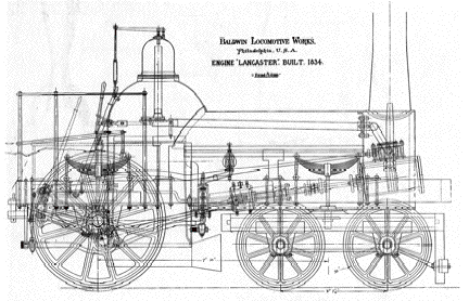
The “Lancaster”, 1834
From John
White
The
Lancaster was Baldwin’s third locomotive – built in 1834. The boiler was
a simple Bury type with a D-shaped firebox. The copper safety-valve column over
the dome could be unbolted, thus opening a manhole for throttle and crown-bar
maintenance. The throttle, located at the base of the dome, was a simple slide
valve with three small rectangular openings. No records exist stating the
number and size of tubes employed by the Lancaster, but a second-class Baldwin
4-2-0 of 1838 was noted as having 118 copper tubes 1-1/2 inches in diameter.
The smokebox is round, an interesting departure from the common idea that round
smokeboxes did not come into being until the introduction of the cylinder
saddle.
The
frame was wooden and was mounted outside of the wheels. No inside
"safety" frames were used as on the English crank-axle engines. The
frame was not clad with iron as was the practice for later Baldwin engines.
Baldwin's
celebrated half-crank axle was used on the Lancaster. One half of the crank
axle is omitted and its place is taken by the driving wheel. The Journal of the
Franklin Institute, May, 1835, noted the advantages as follows: "The power
of the engine is applied directly to the wheel, without the intervention of an
arm of the crank thus diminishing the strain upon the axle, and consequently,
lessening its liability to be broken. By this means, also, Mr. Baldwin has, in
some measure, obviated the tendency of the driving wheels to twist upon the
axles, and become loose; a very general and troublesome defect of
locomotives." Other advantages were the possibility of wider boilers and
the placement of the driving wheels behind the firebox since the connecting rod
could pass between the boiler and frame. As good as this arrangement might appear
to be, it defeated the two major advantages of inside connection - steady running and insulated
cylinders. The cranks were at a great distance from the engine's center line
and the cylinders were outside of the smokebox.
The
truck was wood-framed with outside bearings. The forward weight of the engine
was transferred to the truck by the bearing pin of the leaf spring attached to
the main frame. The truck center pin was merely a pintle and did not carry any
weight. It was placed a few inches behind the center of the truck in order to
shorten the rigid wheel base.
The
wheels were of cast iron in a T spoke pattern, with the ribs facing inside. The
driving wheels had wrought-iron tires.
The
valve gear is based on the motion devised by J. and C. Carmichael of Dundee,
Scotland, in 1818. Joseph Harrison stated that a similar mechanism was used on
early Delaware River ferries, and this may be where Baldwin got the idea for
his locomotive valve gear. It is about the simplest motion that provides
forward and reverse movement. A single fixed eccentric on the driving-wheel
axle drives a girder-frame eccentric rod. The rod has two gabs, one facing the
other. The rocker has two corresponding pins, one of which the upper or lower
gab engages for forward or reverse motion.
The
crosshead and guide are set back a considerable distance from the cylinder.
This allowed convenient attachment to the frame and boiler and also helped to
shorten the connecting rod. It should be noted that, since the driving wheels
are behind the firebox, an unusually long connecting rod would be required if
the crosshead guide were conventionally placed. The diamond-shaped crosshead
guide also served as the feed-water pump body. The check-valve body at the end
of the guide feed-water pump is held together by a stirrup. This permitted
quick disassembly for cleaning out any obstructions clogging the check valves.
The
crosshead and guide were massively made, not only to accommodate the pump, but
also to withstand the racking strain imposed on the mechanism because it was
not in line with the piston rod. This curious arrangement was used regularly by
Baldwin through the 1840's. It was used as late as 1860 on the Active, a small
four-wheel locomotive built for the Philadelphia and Reading Railroad.
Dimensions of the Lancaster
Cylinders 9" x 16"
Wheels 54”
Weight 7-1/2 tons
Steam pressure
120 lbs. per sq. in.
Return
to Pictorial Catalogue of Steam Engines
About
the Hopkin Thomas Project
Rev.
April 2010