The Evolution of the American Locomotive.
By HERBERT T. WALKER.
Member of the National Museum Committee—England
Source: Scientific American Supplement—April
24, 1897
To write a short article on the evolution of the most scientific and wonderful form of the steam engine is not, by any means, an easy task; for not only is the quantity of information on the subject enormous, but it is scattered over a vast area, which makes it difficult to collect and classify and still more difficult to condense and present to the average reader in a way that shall be interesting without going too much into technical details.
It is to be deplored that no history worthy the name has yet been written of the American locomotive. Many short articles and fragmentary accounts of certain old engines have appeared in technical periodicals and some books have been written describing engines of a certain period, or those constructed by a particular firm of engine builders, but, valuable as these works are, none of them have attempted to deal with the subject in either a comprehensive manner or from an impartial standpoint.
Probably the best outline history of the American locomotive will be found in the opening pages of Zerah Colburn's "Locomotive Engineering and Mechanism of Railways," 1871. This is a standard English text book, and it is worthy of note that Mr. Colburn was an American.
The want of a good history is to be further regretted for the reason that drawings of many important locomotives have now become destroyed or lost and their designers and builders have since passed away. An illustration of this point can be made by quoting a passage from a letter received by the author front one of the largest locomotive works in America, in response to a request made by him for certain information:
"We can find no drawings or tracings of the engine you refer to. At the time that engine was built full sets of drawings were probably never made. Full size sketches on boards were often made use of for important parts, sometimes half size on long rolls of paper, and the minor parts, even boilers, were made front pen sketches. Many of the half size drawings on paper, of the engines built in early days, have been defaced, torn and thrown away many years ago."
Even in cases where drawings have been preserved they have been found to be incorrect in details, because complete plans of many engines were never drawn, or if they were, alterations and additions were made during the building of the engines without such changes being noted on the drawings. This is a fault that even modern engineers and draughtsmen are not free from.
In the present article an attempt will be made to trace the progress of the American locomotive from the crude machine of about ninety years ago to the magnificent engine of modern tunes, passing but lightly over all sporadic or transitory forms and dealing principally with some of the earliest engines possessing details of construction that go to make the locomotive of the present day a mechanical and commercial success.
Richard Trevithick, of Cornwall, England, was undoubtedly the father of the locomotive. In the year 1803 he built a tramway engine having a horizontal cylinder connected by gear wheels to the driving wheels; he employed high pressure steam and turned the exhaust steam into the chimney by means of a pipe which he called the "blast pipe." On February 24, 1804, this engine was tried on the Penydarran tramroad, in Wales, and conveyed a load of ten tons of bar iron and about seventy passengers to Merthyr Tydvil, a distance of nine miles. The locomotive worked satisfactorily from a mechanical point of view, but commercially it was not a success, being more expensive than horse traction. [This engine was illustrated in the Scientific American Supplement, April 7, 1894].
No essay on our subject would be complete without mentioning the name of Oliver Evans, although his machine was not, strictly speaking, a locomotive engine, but it was the first carriage propelled by steam in America. The name of this curious machine was Eructor Amphibolis, and it was built for dredging purposes, being mounted on a scow or lighter having four carrying wheels. The engine had a walking beam and fly wheel communicating motion to the carrying wheels by rope gearing. Evans was thus enabled to transport the machine by its steam power from his shop in Philadelphia for some distance over rough roads to the river Schuylkill, which it navigated (by means of a paddle wheel) to its mouth, whence it ascended the Delaware to a point where it was set to work dredging. [This engine was illustrated in the Scientific American, April 3, 1847]. This was in the year 1804, and for the next twenty years Blenkinsop, Hedley, Hackwortb and Stephenson were bending all their energies to develop practical locomotives.
The next attempt at steam locomotion in America appears to have been in the year 1825, when Col. John Stevens, of Hoboken, N. J., designed and built a rack rail engine for the purpose of exhibiting to a committee of the Pennsylvania Society for Internal Improvement when the question of constructing a railroad from Philadelphia to Columbia was being considered. This was the first steam engine that carried passengers on a track in the United States, and is shown in Fig. 1.
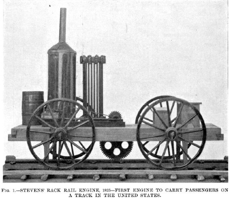
The following extract from a letter dated March 30, 1883, from Mr. F. B. Stevens (Colonel Stevens' grandson) addressed to Mr. J. E. Watkins, Curator of the National Museum, Washington, describing the locomotive of 1825, will be of interest:
"The track was laid on wooden stringers capped with thin iron, the gage being about that usual on ordinary roads or turnpikes. A cast iron rack was laid in the center of track, and into the teeth of this rack a cog wheel, driven by the engine, geared. The engine had only a single cylinder, which was exactly horizontal, resting on the main frame and was from four to five inches in diameter and about one foot stroke. The boiler was formed by a number of vertical tubes each about 1¼ inches external diameter and 4½ feet long. These tubes were set closely together in a circle, surrounding and inclosing a circular grate of about ten inches in diameter. This boiler was inclosed by a jacket of thin sheet iron, which was surmounted by a conical hood on which the smoke stack rested. The fuel was wood, which was dropped on to the grate through a door in the hood. The boiler with its jacket and stack presented very much the outside appearance of the small vertical flue boilers now in use.
"The engine was set on four wooden wheels about four feet in diameter.
"I have an impression that friction wheels of small diameter and having their axes vertical were used to keep the engine on the track, but my recollection is not at all distinct on this point. The tires were without flanges, the wheels being the ordinary wagon wheels."
A full size model of this engine was shown at the Columbian Exposition of 1893 with the tubes placed outside for the purpose of exhibition, as seen in the illustration.
But the first practical locomotives were imported from England. With however much pride (and justly) we Americans may point to our modern engines, some of which are the fastest and most powerful in the world, we must not forget that the cradle of the locomotive was in Great Britain, and that long before any such machine was seen in this country, stalwart mechanics on the bleak hills of northern England and Wales had sweated and toiled their lives away in the face of difficulties and discouragements of which we know nothing; and, with scarcely one of the appliances now commonly found in machine shops, had produced successful locomotives for hauling coal and freight trains. In the year 1825 the Stockton and Darlington Railway was opened for traffic, with George Stephenson's engine Locomotion, and from that time the steam passenger railroad was an established fact.
From Stretton's valuable and interesting book, "The Locomotive Engine and its Development," we learn that early in the year 1828 the Delaware and Hudson Canal Company, having heard of the success of the Stockton and Darlington Railway, sent Mr. Horatio Allen over to England with instructions to obtain information and purchase rails and locomotives. He placed orders for some engines with Messrs. Foster, Rastrick & Company, of Stourbridge, and also with George Stephenson. Stephenson's engine was named America; it was built in 1828, and arrived in New York on board the ship Columbia about the middle of January, 1829. It was the first practical locomotive seen in this country and is illustrated by Fig. 2, which is a copy of one of Stephenson's working drawings. Although this engine was the first to arrive, it was not the first to be used, as will be seen later on. Following are some of the principal dimensions of America: Diameter of boiler, 4 feet 1 inch. Length, 9 feet 6 inches. Dimensions of fire place, 4 feet by 3 feet. Diameter of cylinders, 9 inches by 24 inch stroke. Wheels (wood), diameter 4 feet. Angle of cylinders to the horizontal, 33°. Diameter of tubes, 1 foot 7 inches. Number of tubes, 2. It had no smokebox, the two fire tubes opening directly into the chimney base.
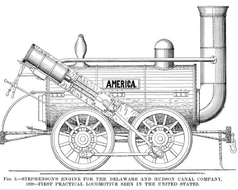
All the early engines designed by Stephenson had frames made of bar iron, but about the year 1826 he adopted a composite frame; the frame connecting the wheels and supporting the boiler being of bar iron as usual, with the addition of a plate iron frame carrying the cylinders and motion, as seen in America. While this construction possesses grave faults, it illustrates a step in the evolution of the locomotive frame, for in 1830 Stephenson abandoned the bar frame and introduced a double plate frame with an oak beam fastened in between the plates. This was called the "sandwich" frame and was used in England for many years, until the oak filling was finally discarded and the frames made of iron plates alone: Thus, the plate frame of the English locomotive of to-day is a development of the cylinder frame of America. On the other hand, American builders, while they used the sandwich frame to a limited extent, soon selected the bar frame as better adapted to American requirements on account of its superior flexibility on a rough track and comparative low cost, and this bar frame is one of the chief characteristics of the modern American locomotive.
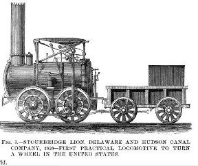
Messrs. Foster & Rastrick's engine, the Stourbridge Lion, is shown in Fig. 3, and was also built in 1828, arriving in New York May, 1829. It was tried for the first time August 9, 1829, being driven by Horatio Allen on a section of the Delaware and Hudson Canal Company's railroad and was the first practical locomotive ever run on a railroad in America. As it was too heavy (7 tons) for the very light track of that period, it was soon withdrawn from traction service. The boiler was tubular and the exhaust steam was carried into the chimney by a pipe in front of the smoke box, as shown. It had vertical cylinders of 36 inches stroke, with "grasshopper" beams and connecting rods, thereby imparting an up and down movement to the driving wheels, a serious defect in a locomotive, as a vertical pull on the cranks is hard on the track and makes the engine unsteady.
In this respect also Stephenson's America (Fig. 2) is worthy a little study, as it is one of the earliest improvements he made in the locomotive engine. It will be seen that the piston rods communicate motion to the cranks by connecting rods without any intermediate gearing (this plan was first used by him in the year 1826), and thus we have one of the earliest examples of a direct connected four coupled engine as now in use all over the world.
We now come to the year 1829, which was a memorable one in railway history, but before describing the principal event of that period it is necessary to note in passing that Peter Cooper built an experimental engine named Tom Thumb. This engine had an upright boiler 20 inches in diameter by 5 feet high, with gun barrels for tubes. It had a single cylinder 3¼ inches diameter by 14½ inches stroke. This engine was tried August 28,1830, on the Baltimore and Ohio Railroad, and with a load of 4½ tons it made 13 miles in 1 hour and 15 minutes, the best time for a single mile being 3¼ minutes.
In the year 1829 George Stephenson placed his world renowned Rocket on the tracks of the Liverpool and Manchester Railway. Although this was only about a year after America was built, the Rocket was a vast improvement on that engine, having a multi-tubular boiler (tubes were of copper) with a fire box riveted to the end thereof, and surrounded with water, inclined cylinders with direct connection between the piston rods and crank pins on a single pair of driving wheels, and the exhaust steam was turned into the chimney through a blast nozzle. In short, it possessed all the essential features of the modern locomotive. [This engine was illustrated in the Scientific American Supplement, April 7, 1894]. At the celebrated Rainhill trials, commencing October 8, 1829, it attained a maximum speed of 24 miles an hour, and is credited with covering a mile in 60 seconds when running without a train.
This engine is preserved in the South Kensington Museum, London, and is generally regarded as the most interesting locomotive in the world, not only for the reasons above named, but also for the fact that its success went a great way to silence the opposition to railways; an opposition that is hard for us to realize at the present day. The early locomotives were contemptuously called "steam pots," by the stage coach and canal proprietors, and they, together with other interested parties, to say nothing of the large class of people who objected to innovations on general principles, made the work of the first railway mechanical engineers one of extraordinary difficulty. It was not an uncommon thing for the engine men to be pelted with stones and brickbats when on a journey, and George Stephenson himself was in danger of his life on more than one occasion. Logs of wood, etc., were frequently placed on the track in front of an approaching train, which was quite serious, as, in those days of insufficient brake power and cumbersome reversing gear, it was almost impossible to stop the engine in time. Even some of the civil engineers of that day were unfavorable to locomotives, as, in their opinion, the lines could be worked more cheaply and better by horses. With a few brilliant exceptions, the English landed gentry were opposed to Stephenson and his infernal machines, a certain nobleman, in the course of a public speech, declaring that he "would rather meet a highwayman on the road than an engineer." The absurd and exasperating questions put to Stephenson by Parliamentary lawyers when early railway bills were introduced are matters of history.
We will now re-cross the Atlantic and see what the Americans were doing about this time. In sharp contrast to the general opposition which the indomitable Stephenson and the handful of enterprising merchants and capitalists who supported him had to fight against, it is refreshing to read that, as Mr. Charles Francis Adams has expressed it, [See "Railroads: There Origins and Problems"] "All through the time during which Stephenson was fighting the battle of the locomotive, America, as if in anticipation of his victory, was building railroads. . . The country, therefore, was not only ripe to accept the results of the Rainhill contest, but it was anticipating them with eager hope." On the fourth of July, 1828, the construction of the Baltimore and Ohio Railroad was begun, the first act being performed by the venerable Charles Carroll, of Carrollton, the only then surviving signer of the Declaration of Independence. At the close of the ceremony of breaking ground Mr. Carroll said, "I consider this among the most important acts of my life, second only to that of signing the Declaration of Independence, if even second to that."
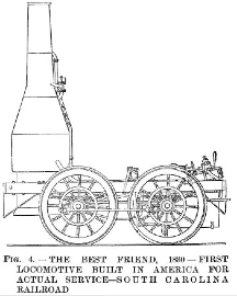
The American mechanics were also following closely on the heels of their English brothers, and in 1830 the South Carolina Railroad Company contracted with Mr. E. L. Miller to build a locomotive which was named the Best Friend. It was the first locomotive ever built in America for actual service upon a railroad, and was designed by Adam Hall and constructed by the West Point Foundry Association, foot of Beach Street, New York City. It was a four coupled, inside connected engine, as shown in Fig. 4, which is reproduced from a copy of the original drawing. The cylinders were 6 inches in diameter by 16 inches stroke, driving wheels 4 feet 9 inches diameter, weight 4½ tons. The boiler was vertical, and was totally destroyed by explosion on June 7, 1831, being, it is said, the first locomotive boiler explosion on record.
The second locomotive built for actual service in the United States was the West Point, in 1830-31; it was built for the same railroad and at the same shops as the Best Friend. This engine had a horizontal tubular boiler with tubes 2½ inches in diameter and 6 feet long. Four coupled driving wheels 4 feet 9 inches diameter. Inside connected cylinders 6 inches diameter by 16 inches stroke. With 5 cars containing 117 passengers this engine made 2½ miles in 8 minutes.
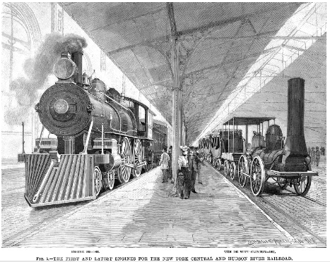
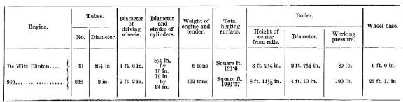
The third American engine built for actual service was the De Witt Clinton. This engine was also constructed at the West Point Foundry in 1831, and was trade for the Mohawk and Hudson Railroad, now a part of the New York Central and Hudson River Railroad, to the order of Mr. John B. Jervis, chief engineer of the former road. A full size model of this engine was exhibited at the Columbian Exposition, 1893, and is illustrated on the right hand side of Fig. 5. The engine on the opposite side of the cut is No. 999, and will be described in its proper place later on. The outward appearance of De Witt Clinton was very similar to America, Fig. 2, but the cylinders were inside connected and the frames were of wood, reinforced with iron. We also notice that it had a rudimentary smoke box. The boiler had 30 copper tubes, 2½ inches diameter, wheels 4 feet 6 inches diameter, cylinders 5½ inches diameter by 16 inches stroke, weight, of engine and tender about 6 tons.
The first regular trip was made between Albany and Schenectady, August 9, 1831, when, with a load of three coaches, a maximum speed of 15 miles an hour was attained, but, alone, the engine was run at a speed of 40 miles an hour. The conductor had a small seat on the rear of the tender and gave the signal for starting by blowing a tin horn. We are told that "the fuel used was dry pitch pine, and as there was no spark arrester on the stack, the sparks poured back on the passengers in such a volume that they raised their umbrellas as shields. The covers were soon burned off these, and each man whipped his neighbor's clothes to put out the fire started by the hot cinders."
The illustration shows the engine with a large steam dome, but in an official drawing published in the Railroad Gazette of May 25, 1883 (which also contains authentic drawings of the Best Friend and West Point), the engine is without a steam dome. The New York Central and Hudson River Railroad Company's description gives the diameter of driving wheels as 4 feet 6 inches, but the wheels on the above named drawing scale 5 feet. There are other discrepancies, but, nevertheless, Fig. 5 may be accepted as a fair representation of the De Witt Clinton.
Mention having been made of the conductor blowing a tin horn, we note, by the way, that an old print showing Stephenson's Planet on Liverpool and Manchester Railway, year 1830, represents the engine driver blowing a bugle after the manner of a stage coach guard. The first whistle was a steam trumpet placed by George Stephenson on the Samson, a freight engine for the Leicester and Swannington Railway, in May, 1833.
In the year 1831 a curious design of locomotive was introduced by Messrs. Davis & Gartner, of York, Pa. It was run on the Baltimore and Ohio Railroad. The boiler and cylinders were upright, with four coupled wheels, 30 in. in diameter, but it was altered considerably after being placed on the road. The Atlantic was afterward built by the same firm, and was a much improved engine. Its boiler and cylinders were also vertical, beams being used to transmit power to the cranks, which were on a shaft connected by toothed wheels to an intermediate shaft having outside cranks coupled to the driving wheels. In consequence of the peculiar shape and movement of the beams, the engines were called "Grasshoppers." Fig. 6 shows one of this class manufactured by Gillingham & Winans for the Baltimore and Ohio Railroad in the year 1835. Wheels 36 in. in diameter; boiler 52 in. in diameter, containing 400 tubes 1 in. in diameter and 3 ft. 2 in. long. Diameter of cylinders 10 in. by 24 in. stroke. Weight of engine and tender; 7 tons 5 cwt. empty. The circular structure at the base of the small chimney is a fan which was driven by the exhaust steam before it escaped.
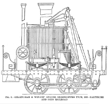
This fan was for urging the fire. It was, however, subsequently removed and the exhaust steam turned into the large chimney in the usual way. This engine and seven other similar ones were in constant service on the Baltimore and Ohio Railroad for a period of over fifty years. Some of them are now in the Field Museum.
Fig. 7 shows the celebrated John Bull, which is now in the National Museum, Washington, D. C. It was the first engine for the Camden and Amboy Railroad, now a part of the Pennsylvania Railroad. It was designed and built by Stephenson & Company, of Newcastle upon Tyne. This engine represents another step in locomotive construction, for while it somewhat resembles the De Witt Clinton, the cylinders are placed at the smoke box end of the engine, and the smoke box is of the same pattern as used to-day; both these improvements were embodied in the before mentioned Planet engine designed by Stephenson early in the year 1830.
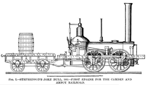
This engine (John Bull) was ordered by Robert L. Stevens, President of the Camden and Amboy Railroad, from Messrs. Stephenson & Company, in December, 1830, and was shipped to Bordentown, N. J., where it arrived in August, 1831. The cut (Fig. 7) was made from a drawing now in the Washington Museum, and is said to be an exact representation of the engine when it arrived in this country; but in a copy of one of Stephenson's working drawings in the author's possession the engine is shown with a chimney of different shape and with a different arrangement of safety valves. This matter is small in itself, but illustrates one of the many difficulties that confront a writer who undertakes to show and describe locomotives built so many years ago.
The engine was originally named Stevens, but on its arrival in this country the railroad company called it John Bull, and it was entered in their books as "No. 1." It was put in service November 12, 1831, at Bordentown, N.J., where the Railroad Monument now stands. The leading dimensions were as follows:
Weight about 10 tons, boiler, 3 ft. 6 in. diameter; cylinders, 9 in., diameter by 20 in. stroke. Four coupled wheels 4 ft. 6 in. diameter, with cast iron hubs and locust wood spokes and felloes. Tires of wrought iron ¾ in. thick; sixty-two tubes, 7 ft. 6 in. long by 2 in. diameter. Furnace 3 ft. 7 in. long by 3 ft. 2 in. high (for burning wood). Heating surface of tubes, 213 sq. ft.; of firebox, 36 sq. ft. Total heating surface, 249 sq. ft. The firebox was of the dome or Bury pattern. The reversing gear was complicated, the two eccentrics being secured to a sleeve or barrel, which fitted loosely on the crank shaft. A treadle was used to change the position of this loose eccentric sleeve, moving it to the right or left lengthwise on the shaft. Two carriers were secured firmly to the shaft (one on each side of the eccentrics); one carrier worked the engine ahead, the other back, so that when the eccentrics were half way between the two carriers, the axle turned without moving them, and the engine was out of gear. In order to reverse, the engine driver placed his foot on the treadle (which is between the firebox and the handle of the feed water cock), thereby disengaging the eccentrics from the carriers he then pulled a small handle on the right side of the boiler and so lifted the small ends of the eccentric rods (which passed forward to the rocking shaft on the front of the engine) clear of the valve stems, after which he took hold of the two valve levers on the foot plate, and by moving them back and forth admitted steam to the cylinders by the hand gear; when the engine was fairly started, he, by means of the treadle, caused the eccentrics to engage with the opposite carrier, and it continued to actuate the valves.
Soon after the engine arrived, the Camden and Amboy mechanics made the following changes and additions: As the railroad curves were very sharp, the coupling rods and cranks were removed and a lateral play of 1-½ in. given to the leading axle, to which a cowcatcher was connected. The wooden wheels were replaced by cast iron wheels. The dome was moved forward to the former man hole and the boiler lagged with wood. A bell was placed on the boiler and a headlight on the smoke box. A new tender was subsequently built, having a small cab on the rear for the accommodation of a brakeman, who, if anything went wrong with the cars, could signal the engine driver to stop. The engine then presented the appearance shown in Fig. 8. From a cut in the Railroad Gazette of March 9, 1877. it appears that a cab and a large wood-burning chimney were subsequently added, but both these were removed some time before the engine was placed in the United States National Museum.
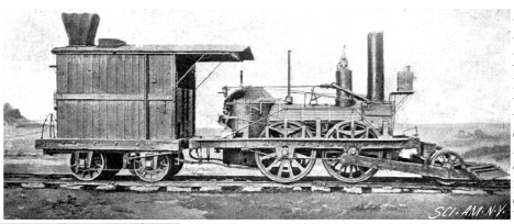
As far as the writer can discover, this was the first engine equipped with a bell, headlight and cowcatcher, although bells were used on English locomotives as far back as 1827.
This remarkable locomotive was exhibited at the Philadelphia Exposition of 1876, and again at the Chicago Exposition of Railway Appliances in 1883, and lastly, at the Columbian Exposition of 1893. Leaving New York City under steam April 17, 1893, it hauled "the John Bull train" of two cars 912 miles, without assistance, to Chicago, arriving April 22, and meeting with continued ovation over the entire route. It formed part of the Pennsylvania Railroad Company's exhibit, and was one of the great attractions of the World's Fair, carrying over fifty thousand passengers over the exhibition tracks in the terminal station yard. The engine left Chicago again under steam December 5, 1893, coming east over the Pennsylvania lines via the Southwest system to Pittsburgh, and through Altoona, Harrisburg and Baltimore to Washington, arriving there December 13, 1893. This was a very good performance for a locomotive sixty-two years of age. It was then returned to the museum at Washington, where it will remain permanently.
In the year 1832, William T. James, of New York, invented a very important improvement in locomotive valve gear, viz., the link motion. This reversing and expansion gear is the embodiment of "the beauty of simplicity," for, while the valve gears up to that time and for years afterward were largely made up of a complication of rods and levers, as in the John Bull, they only served to reverse the engine and did not admit of the steam being worked with a varying degree of cut-off and expansion, so essential to the economical working of a locomotive. James' design was nothing more nor less than connecting the small ends of the fore and back gear eccentric rods by a curved link, the curve being concave toward the eccentrics, said link having a slot which engaged a slide block, fastened to the valve stem. By a hand lever the engine driver could move the link up or down, thus causing either the fore or back gear eccentric to communicate motion to the slide valve and so control the direction of the engine's motion.
The effect of this device as a cut-off mechanism is that when the slide block is in the center of the link, midway between the two eccentric rods, the engine will be in mid-gear, but on the link being moved so as to bring one of the eccentric rods - ”say the fore gear rod” - opposite to the block, and steam being admitted, the engine will move forward and the valve will cut off the steam when the piston is nearly at the end of its stroke; if the link is moved so that the block will occupy a position between the eccentric rod and the center of the link, the slide valve will cut the steam off at an earlier period of the piston's stroke and so leave the rest of the stroke to be performed by the expansion of the steam, and the more nearly the center of the link is brought to the slide block the shorter becomes the travel of the valve and the earlier will the steam be cut off. Thus, the rate of cut-off and degree of expansion, either for fore or back gear, can be regulated while the engine is running and according to the work it has to do.
This is one of the simplest inventions in the world. There is no valve gear equal to it, and it is used on nearly every locomotive to-day.
James' engine of 1832 (see Fig. 9), fitted with the link motion, was intended for the Baltimore and Ohio Railroad. The boiler was vertical and of weak construction. The cylinders were 8 in. in diameter by 12 in. stroke and the slide valves had ½ in. lap at each end. The gross weight was 3-½ tons. There were four wheels (not coupled) 3 ft. in diameter.
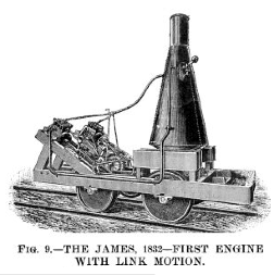
A representative of the American Railroad Journal visited Mr. James' shop at 40 Eldridge Street, New York City, to examine his wonderful locomotive which had just been completed. He states that the engine was run on a track fifty feet in length, backward and forward eight times in 63 seconds, including stops: Although he does not describe the valve motion, it is evident that none but the most efficient reversing gear, such as the link motion is, would have secured such a result. He also states that Mr. James (a few days later) placed the engine on wheels without flanges and ran it over the pavements and Third Avenue to Yorkville, about five miles, where he took breakfast and then returned to the city. [American Railroad Journal, October 29, 1832.]
It may be mentioned that a weight, which can be seen in Fig. 9, was fixed on the reversing lever to retain the links in position for fore or back gear, there being no means of fixing them in an intermediate position; but Mr. Samuel B. Dougherty (subsequently locomotive superintendent of the Camden and Amboy Railroad), who assisted in the construction of this engine, and wrote a description of it in May; 1858, said that "in setting the eccentrics we found the link would cut off, and we so used it on the engine to expand from different points." [Colburn's Locomotive Engineering and Mechanism of Railways, 1871.]
Before this engine was sent to Baltimore it was run for some time on the Harlem Railroad, where it worked satisfactorily. In 1833 it was forwarded to its destination, but, soon after having been placed in regular service, the boiler exploded and the engine was totally destroyed. A full size model of this engine was sent to the Columbian Exposition.
Strange to say, the link motion after this appears to have dropped out of sight, American engineers using a variety of fork or hook motions, all more or less objectionable, until ten years later, when we will again take the matter up in its chronological order.
In the year 1832, Matthew
W. Baldwin, founder of the famous Baldwin Locomotive Works, received an order
for a locomotive from the Philadelphia, Germantown and Norristown Railroad
Company, whose short line of six miles was operated by horse power. He, in
company with his friend, Mr. Peale, went to Bordentown to examine one of Stephenson's
engines (probably the John Bull) on the Camden and Amboy Railroad, and made
some memoranda of its principal dimensions. After many difficulties had been
surmounted, he built a locomotive and christened it Old Ironsides. It was tried
on the road November 23, 1832, and is shown in Fig. 10.
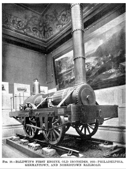
A full size model of this engine is now in the Field Columbian Museum, Chicago. Its chief dimensions were as follows: Driving wheels, 4 ft. 6 in. diameter; leading wheels, 3 ft. 9 in. diameter; cylinders, 9-½ in. in diameter by 18 in. stroke. They were attached horizontally to the outside of the smoke box, just inside the frames, which were of wood, with iron pedestals. The wheels were made with heavy cast iron hubs, wooden spokes and rims, and wrought iron tires. The boiler was 30 in. in diameter, and contained 72 copper tubes 1-½ in. diameter and 7 ft. long. The reversing gear consisted of a single eccentric, with a double latch eccentric rod gearing alternately on pins on the upper and lower ends of the arms of a rocking shaft. It will be seen that the Ironsides closely resembled the John Bull, except that the leading wheels were smaller than the driving wheels, and the firebox was of the regular Stephenson type instead of the dome or Bury pattern.
This engine weighed about 8 tons and was able to draw 30 tons on a level. It was the first locomotive Mr. Baldwin ever built, and did duty on the Germantown and other roads for over a score of years, and was seen by Zerah Colburn at the Fitchburg Railroad station, Boston, in 1853. It is but justice to Baldwin to add that he soon abandoned the English design of the Ironsides and quickly placed himself at the front in American locomotive practice, some of the finest engines in their day having been built by him.
American designs very soon began to depart from their British prototypes, and a process of adaptation to the existing conditions of the railroads in this country followed.
Until recently, a marked feature of difference between American and English locomotives has been the use of the swiveling truck under the former to facilitate the passage of the engine around curves. An English patent dated December 30, 1812, was granted to William and Edward Chapman for a four wheeled swiveling truck. In the year 1815, Messrs. Blackett & Hedley constructed a locomotive named Puffing Billy for the Wylam Colliery Railway, having two four wheeled trucks, but the truck did not come into general use in England until about thirty years ago.
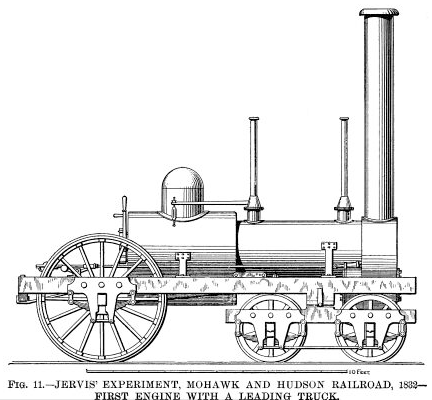
In the year 1831 Mr. Horatio Allen designed an engine with two trucks for the South Carolina Railroad, of which he was then the chief engineer, but to Mr. John B. Jervis, chief engineer of the Mohawk and Hudson Railroad, belongs the honor of designing the first engine with a leading truck swiveling on a center pin, as generally used the world over to-day. This was in the year 1831; and in the year 1832 his engine Experiment was put on the above named road for regular service. The cylinders were 9-and-five-eighths in. in diameter by 16 in. stroke. Diameter of driving wheels, 5 ft. Grate 5 ft. long, for burning anthracite coal. Weight 7-½ tons. This important locomotive is shown in Fig. 11. It was the ordinary uncoupled or single driving wheel engine as commonly used at that period, and, as it presents no novel features aside from the truck, further description is unnecessary. [An interesting letter from Mr. Jervis, with an illustration of his Experiment, appeared in the Railroad Gazette, Vols. III and IV.]
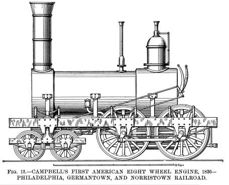
As time went on, it was found that one pair of driving wheels did not furnish sufficient adhesion and power for the ever increasing loads to be hauled, and, therefore, the next step was to utilize the four coupled wheels embodied in some of the engines previously illustrated and combine them with the leading truck. This arrangement was patented in 1836 by Henry R. Campbell, chief engineer of the Germantown Railroad, "in order to distribute the weight of the engine upon the rails more completely." In the same year he designed the freight engine shown in Fig. 12 (the previous engines were used for both freight and passenger trains), and thus we have the first American eight wheeled engine. It had cylinders 14 in. diameter by 16 in. stroke. Driving wheels 4 ft. 6 in. diameter, the forward pair being without flanges. Gross weight about 12 tons, the adhesive weight being 8 tons. Heating surface about 725 sq. ft. It was tried on the Philadelphia and Germantown Railroad, May 8, 1837, but was found to be a "hard rider," for the reason that it had no means of equalizing the weight on the driving wheels so as to meet the various undulations in the track, and it would also appear from the drawing that the truck had no center pivot, the frame being made with rtical projections sliding in pedestals on the main frame, and being connected thereto by side springs. If this was the case, the truck could only vibrate in a vertical plane and could not turn horizontally. To remedy the defects of the Campbell engine, Messrs. Garret & Eastwick, of Philadelphia, completed in 1837 a new style of freight locomotive for the Beaver Meadow (now the Lehigh Valley) Railroad Company. This engine, named Hercules, had a separate rectangular frame for the four coupled wheels, this frame being pivoted on each side to the main frame by springs and journal boxes sliding vertically in pedestals on the main frame. Thus the separate frame was enabled to move up and down as well as to swing vertically on its center, and so permit the four driving wheels to accommodate themselves to the unevenness of the track, provided the undulations were alike on both rails, which of course, never happened, and the "separate frame" got badly racked in consequence.
To overcome this objection, Mr. Joseph Harrison, Jr., of the firm of Eastwick & Harrison, patented in 1838 an improvement for equalizing the weight on the wheels of locomotive engines. The preferred form consisted in placing the driving axle bearings in pedestals on the main frame in the usual manner (the separate frame being discarded), and, instead of connecting the driving wheel axle boxes directly to the frame by springs (as in Campbell's engine), a horizontal beam or lever was introduced, having a central pivot linked to a spring fastened to the frame, and its ends provided with rods that passed down through the frame and abutted on said axle boxes. There were two of these levers, one on each side of the engine. They vibrated separately and thus met all the unevenness in both rails. In all equalized engines now built in this country or in Europe this device of Mr. Harrison's is used in one or other of the different ways indicated in his patent. [The Locomotive Engine, by Joseph Harrison, Jr.]
These compensating levers are known as equalizers, because' when running on an uneven track, they distribute the shock or jar equally over all the wheels so connected.
Fig. 13 is a side elevation of this important engine as rearranged with Harrison's equalizing levers, and a full size model of it is now in the Field Museum, Chicago. The engine had 12 in. cylinders by 18 in. stroke, and four coupled driving wheels 3 ft. 8 in. diameter. Its gross weight was about 14 tons, of which 9 tons were available for adhesion. With steam of 90 lb. pressure per square inch (then a common pressure in this country) the engine drew a load of 265 tons, including the tender, up a grade varying from 27 ft. to 35 ft. per mile. The speed was not given, but the other particulars are derived from the report of a committee of the Franklin Institute, dated May 9, 1839.
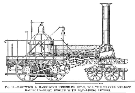
While there is no doubt that Harrison was the original inventor of equalizing levers as used at the present day, it is necessary to call attention to the fact that Timothy Hackworth (Stephenson's great rival) rebuilt a six coupled engine, named Royal George, for the Stockton and Darlington Railway, in the year 1827; each of the middle and back wheels were equalized by a spring in the same way as shown in Fig. 2 of Harrison's specification above referred to. A drawing of the Royal George will be found in Colburn's Locomotive Engineering and Mechanism of Railways, page 21.
Before dismissing the Hercules, we will notice the reversing gear, which was patented by Mr. A. M. Eastwick, July 21, 1835, and is very simple and ingenious. It will be seen by Fig. 13 that the valve chest had two valve stems projecting therefrom. The upper one was for the ordinary slide valve and was connected to a rocking shaft actuated by a single eccentric on the rear axle. The lower one was connected to a movable block working between the slide valve and the cylinder ports. This movable block had four ports, two for fore gear and two for back gear. The fore gear ports (called direct ports) opened directly into the cylinder in the usual way, but the back gear ports (called indirect ports) went but half way through the block, and then turned and passed each other before entering the cylinder. When it was desired to run the engine backward, the block was moved by the hand lever on the foot plate to bring the indirect ports in communication with the cylinder, so that when the slide valve admitted steam to the front port in the block it was conducted to the back end of the cylinder and vice versa. A similar device was patented in England by William Beckett Johnson in the year 1847.
It is interesting to note that Mr. Harrison, in conjunction with Mr. Winans, afterward constructed and worked the rolling stock of the St. Petersburg and Moscow Railway in Russia, and all the engines, nearly 200 in number, originally made at Alexandrowski, near St. Petersburg, were fitted with Eastwick's reversing valve block, and, with the addition of a separate expansion valve, these engines were running as late as the year 1871.
FIG. 14 illustrates the Sandusky, the first locomotive built at the famous Rogers Locomotive Works, Paterson, N. J. At that time the name of the firm was Rogers, Ketchum & Grosvenor, and its founder Thomas Rogers, designed this engine. The late Zerah Colburn remarked that "Thomas Rogers maybe fairly said to have done more for the modern American locomotive than any of his contemporaries."
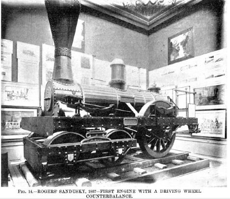
The Sandusky ran its trial trip from Paterson to Jersey City and New Brunswick and back October 6, 1837, its performance being entirely satisfactory. It was intended for the New Jersey Railroad and Transportation Company, but was, however, bought for the Mad River and Lake Erie Railroad by its president, Mr. J. H. James, of Urbana, O. It continued in service many years. The cylinders were 11 in. in diameter by 16 in. stroke. Driving wheels 4 ft. 6 in. diameter; truck wheels 2 ft. 6 in. diameter. The general design did not differ materially from the Experiment (Fig 11), but it is of interest as being the first locomotive with weights on the driving wheels to counterbalance the cranks and connecting rods. For this Mr. Rogers filed a specification in the Patent Office dated July 12,1837, in which he says, "The irregular motion which arises from not having the cranks and connecting rods balanced is attended with much injury to the engine and to the road, and with much loss of power." The driving wheels were of cast iron, with hollow spokes and rims, which at that time was a remarkable novelty. The section of the spokes was of oval form, and the rim of very much the same shape as that which is in common use to-day. In order to counterbalance the parts referred to, the rim of the wheel opposite the crank was cast solid. The importance of counterbalancing was not recognized until several years after it had been introduced by Mr. Rogers, but to-day it would be hard to find a locomotive without counterbalanced driving wheels.
Another sporadic form of locomotive engine was built by Gillingham & Winans, of Baltimore, for the Baltimore and Ohio Railroad, in the year 1838. They had upright boilers, but the cylinders were horizontal and were connected to cranks on an intermediate shaft, which was geared to a second shaft having outside cranks to which the four driving wheels were coupled. These engines were of ungainly form and were nicknamed "crabs," but in the year 1844 Mr. Winans brought out another class of engine retaining substantially the same system of gearing but with eight coupled wheels instead of four, and a horizontal boiler. These engines were ignominiously named "mud diggers," but they did heavy freight service on the Baltimore and Ohio Railroad for many years.
At this period it will be necessary to revisit England to see what was going on in the shops of Robert Stephenson & Company, Newcastle upon Tyne, in 1842. In that year it appears that the link motion was reinvented without previous knowledge of James’ invention. William Howe, a mechanic employed in Stephenson’s shops, decided to place a curved link between the eccentric rods to take the place of the Stephenson "fork motion," then in general use. He made a pencil sketch and wooden model which were shown to Robert Stephenson, who, seeing its merits, ordered it to be fitted to all engines constructed at his works, and from that time it has been known as "Stephenson’s link motion." The first engine equipped with this gear was No. 71, for the North Midland Railway, and commenced to run September 10, 1842. There was a dispute between Howe and an apprentice named Williams, who claimed to have a share in the invention, but as we have not space to enter into the details of the controversy, the reader is referred to Colburn’s "Locomotive Engineering," where the matter is very ably dealt with.
But not even when the link was being used with such remarkable success in England did American engineers recognize its merits, and it was not until 1847 that it was adopted in this country. In the year 1849 Mr. Thomas Rogers introduced it in his practice, fitting a stationary link motion to some engines for the Hudson River Railroad. In this arrangement the curve of the link was convex toward the eccentrics, instead of concave, as in the Stephenson gear, and the link was suspended on a fixed center, the valve rod block being moved up and down instead of the link. This plan was introduced by Sir Daniel Gooch, master mechanic of the Great Western Railway, of England, about the year 1845. In 1850 Mr. Rogers commenced to build engines with the shifting link motion, and soon afterward it came into general use. Other builders, however, strenuously resisted the innovation, and none more so than Mr. Baldwin, who could not be induced to adopt it until the year 1854, when he fitted the link to the Pennsylvania, an engine for the Central Railroad of Georgia.
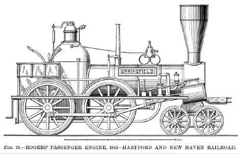
The next example of progress in locomotive construction is illustrated in Fig. 15, which shows a very good engine designed by Mr. Rogers and built at his works, in 1845, for the Hartford and New Haven Railroad. It had equalizing levers between the driving wheel springs, which do not show in the drawing. The truck had side bearings and springs on the sides of truck. The pumps had short stroke and were worked from the crosshead as shown. The cylinders were 11-½ in. diameter by 18 in. stroke. Driving wheels 5 ft. diameter. We notice the supplemental frame that supports the running board. It illustrates the transition from outside to inside framing. The frames were of bar iron and the reversing gear was the hook or fork motion.
The writer has not succeeded in discovering when the first sand boxes were used. The early locomotives were without them. When the engine slipped, the fireman jumped down and threw some gravel on the rails with his shovel, or, failing that, he used the pinch bar, with verbal encouragements, more powerful than polite, from the engine driver. The next step appears to have been a bucket of sand carried on the foot board, and scattered by hand when required. Mr. Baldwin commenced to place sand boxes on his engines in the year 1846 for the Philadelphia and Reading Railroad. The chief objection to sand is that, while it prevents the driving wheels from slipping, it has a retarding effect on the train wheels, which, with a heavy load on a hill, is a very serious drawback. To overcome this, a jet of steam or water has been tried, and with a measure of success, as it is well known that thoroughly wet rails will give almost as good adhesion as when they are perfectly dry. An electric current has been passed through the driving wheels and rails to prevent slipping; but none of these devices are equal to good dry sand.
In the year 1846, Septimus Norris, a brother of William Norris, patented a ten wheel freight engine with six driving wheels combined with a leading truck. Several of these were built for the Philadelphia and Reading Railroad.
An interesting locomotive is illustrated by Fig. 16, which shows one of a class built at the Norris Works about the year 1847, for the Camden and Amboy Railroad. There were several of these engines built, most of them having driving wheels 8 ft. in diameter and cylinders variously 13 in. by 34 in., 13 in. by 38 in. and 14 in. by 38 in. stroke. Their weight was about 22 tons in working trim. This type of engine has the driving wheels behind the firebox and is known as the "Crampton" class, having been patented in 1843 by the late Thomas Russell Crampton, an English engineer of some distinction. He did not, however, originate the idea, as Baldwin built engines with the driving wheels behind the firebox in the year 1833. The advocates of this class of engine claimed that it admitted of driving wheels of practically unlimited diameter, while the boiler could be dropped down to the axles of the carrying wheels, thus enabling an engine with large driving wheels to have a low center of gravity, which was at that time and for years afterward considered necessary for safety at high speeds. Crampton engines never came into general use anywhere except in France, where the "systeme Crampton" was very popular and it is believed that some of the engines are still running.
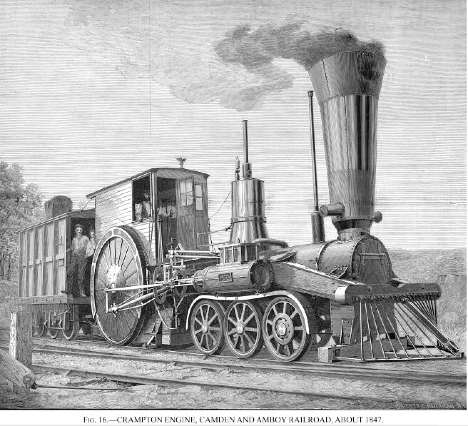
Referring to the example before us (Fig. 16), we are informed that these engines made steam slowly, which was probably caused by the fact that the boilers were small compared with the immense cylinders and driving wheels. Another drawback to them was that they lacked adhesive weight, having only about 8 tons on the driving wheels; it was, therefore, hard to start them with a train, although when under headway they occasionally covered a mile in 53 seconds. But the most serious objection to there was their tendency to run off the track when traveling fast, the chief reason being that the propelling mechanism at the rear end, with unbalanced driving wheels, caused the front end to "nose" or oscillate laterally. It will be observed that the driving wheels had a wood filling between the spokes to prevent "raising dust."
Fig. 17 illustrates a fine engine designed by Mr. McQueen for the Hudson River Railroad (now apart of the New York Central and Hudson River Railroad). It is interesting not only for the excellence of the design, but because it was one of the first engines to do regular everyday express work on the road that now claims to have the fastest regular train in the world. It appears that the Hudson River steamboats, even as far back as 1845, offered great inducements to travelers by reason of their luxurious accommodation and high speeds, and these express trains were put on to compete with them. A writer in the Practical
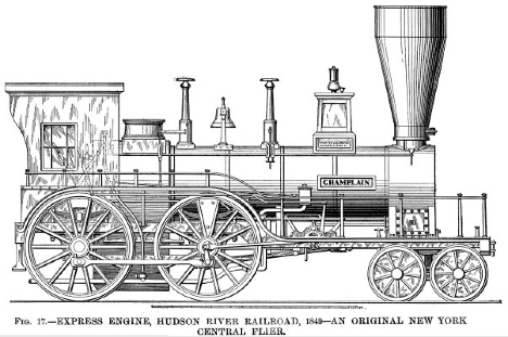
Mechanic’s Journal of 1850-51, in describing this engine, said: "The usual speed of railroads was not so much greater as to induce the passengers to leave the magnificent floating palaces. Great speed must, therefore, be determined on." The result was the Champlain, which commenced working the express trains between Thirty-first Street, New York, and Poughkeepsie, 72 miles, in December, 1849. The distance was covered in 2 hours 25 minutes = 29.79 miles an hour, including twelve stops. The weight of the trains averaged 94 tons, exclusive of engine and tender. The ordinary trains did the same distance in 2 hours 45 minutes.
The Champlain had cylinders 15 in. in diameter by 20 in. stroke. Steam ports, 14 in. by 1 in. Exhaust port, 14 in. by 2 in. Driving wheels, 5 ft. 6 in. in diameter. Heating surface of firebox, 79.43 sq. ft.; of tubes, 824.43 sq. ft.; total heating surface, 903.86 sq. ft. Gross weight of engine, 23-½ tons. The frame was a curious example of the transition from plate to bar, it being made of two plates with a square bar riveted between. The plates were 5 inches deep.
There were two slide valves in. the steam chest; the upper one was a cut-off valve to enable the steam to be worked expansively, and it moved on a fixed perforated plate immediately over the main valve. The former was worked from a return crank on the crank-pin; the main valve was worked from the eccentrics with the V hook motion commonly used at that period. The throw of the main valve was 3-½ in. with five-eighths in. lap, and set with a lead of three-sixteenths in. The expansion valve cut off at half stroke.
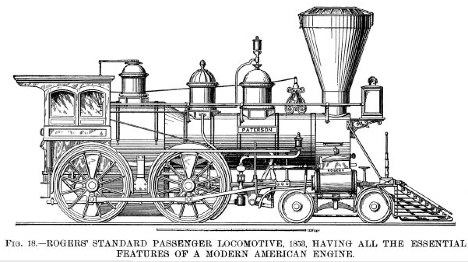
Referring back to Fig. 12, it will be seen that Campbell’s engine, although it has the Stephenson firebox, four coupled driving wheels, with cylinders connected to the forward pair, and a leading truck, does not possess all the essential features of the modern locomotive, because the frames are outside and of plate iron and wood. The cylinders are inside connected, and it has no equalizers. Fig. 13 has outside cylinders, leading truck, inside frames and equalizers, but the frames are of plate iron and wood, the cylinders are connected to the rear driving wheels, and the firebox is of the Bury pattern Fig. 15 has the bar frame, and begins to look more like an American engine, having the equalizers and the cylinders connected to the, forward driving wheels; but the cylinders are inclined, and the outside frame for the running board and objectionable Bury firebox are still retained, and the reversing gear is the hook motion. Engineers up to that time were afraid of spreading the truck wheels too far apart; hence the necessity of inclined cylinders but in 1850 Mr. Rogers designed a spread truck, which permitted the cylinders to be dropped down to a horizontal line, and in the same year the wagon top boiler was introduced in the practice of the Rogers Locomotive Works; and so we have in the year 1853 an engine possessing all the essential features of a modern American locomotive, which is shown in Fig. 18. It had the Stephenson firebox, with the peculiar inclined or tapered joint between it and the barrel of the boiler, making what is known as the wagon top boiler. The latter was an American invention. A large number of these engines were built by Mr. Rogers for various railroads. They had the link motion. The cylinders were 16 in. diameter by 22 in. stroke, and the driving wheels were 5 ft. in diameter, although the size of the latter was varied in different engines.
In 1857 Mr. Bissell patented a four wheeled truck, having its frame extended rearwardly and pivoted to the engine frame. The truck, therefore, swung from this pivot instead of on a central pin, and the engine rested on a pair of V shaped inclined planes
midway between the two axles. The inventor claimed that a truck on his plan adjusted itself to the curvature of the track better than one of the ordinary plan. Mr. Hudson, of the Rogers Locomotive Works, was one of the first to recognize the value of Bissell’s invention, and applied it to a locomotive in 1858. In the same year Bissell patented the single axle or pony truck, as it is often called. This was constructed on substantially the same principle as his four wheeled truck and is now in common use.
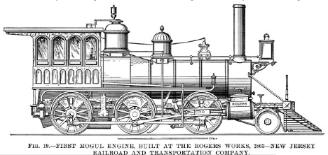
On the death of Mr. Rogers, which occurred in 1856, the business of Rogers, Ketchum & Grosvenor was reorganized under the title of the Rogers Locomotive and Machine Works, and Mr. William S. Hudson was appointed superintendent. Mr. Hudson was a pupil of George Stephenson’s, and was one of the foremost locomotive engineers of his day. Under his supervision, the first Mogul engine, Fig. 19, built at the Rogers works, was completed in 1863 for the New Jersey Railroad and Transportation Company, now the New Jersey part of the Pennsylvania Railroad. This engine had six coupled wheels and the Bissell pony truck previously described, with swing links patented by Mr. Alba F. Smith, and also an equalizing lever from the truck to the springs of the forward driving wheels. This equalizing arrangement was invented and patented by Mr. Hudson. The cylinders were 17 in. diameter by 22 in. stroke. Driving wheels 4 ft. 6 in. in diameter. Weight about 35 tons. A very large proportion of the weight of a Mogul engine rests on the driving wheels, which makes it the most useful and popular freight engine of today.
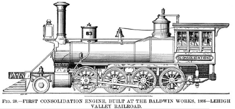
The rapid increase of traffic during the period under notice demanded a still more powerful freight engine, and in order to secure the necessary amount of adhesion, Mr. Alexander Mitchell, master mechanic of the Lehigh and Mahoning Railroad, designed in the year 1866 an eight coupled engine, and it was named Consolidation. This name was suggested by the consolidation of the Lehigh and Mahoning with the Lehigh Valley Railroad, which had just then been consummated.
This historical locomotive is shown in Fig. 20, and it is interesting to note that both the Mogul and Consolidation engines of the present day have not been altered in any essential particular except in dimensions, which reflects great credit on their designers. The Consolidation was built at the Baldwin Locomotive Works, and its principal dimensions were: Cylinders, 20 in. diameter by 24 in. stroke; driving wheels, 48-½ in. in diameter. The pony truck was equalized with the front driving wheels. Weight about 45 tons. The boiler was fed by one injector and two feed pumps; the latter were worked by return cranks on the rear driving wheels, as shown. Pumps have now practically become obsolete. They gave much trouble by freezing in cold weather, and many vexatious delays were caused by "failure of the pumps."
Mr. H. J. Giffard, a French engineer, discovered that the motion imparted by a jet of steam to a surrounding column of water was sufficient to force it into the boiler from which the steam was taken. In July, 1858, he patented his invention of the injector, and the various inspirators now in general use for supplying steam boilers with water are all constructed on the model of the Giffard injector.
In these days of "continuous brakes," it seems remarkable that the early locomotives were absolutely without any retarding mechanism; and even down to the medieval period of railway history, the fastest English trains were run with only a hand brake on the tender, and a similar brake, worked by the guard, in the brake van. When the tender weighed only 10 or 15 tons and the brake van less, this system was woefully inadequate, and many frightful accidents resulted. American trains were far better equipped in this respect, and at a very early period all our cars, both freight and passenger, were provided with hand brakes. In the year 1833, Robert Stephenson patented a steam brake for locomotive engines, and in the following year the device was applied to an engine on the Liverpool and Manchester Railway. It was successful, but, like the link motion, never came into general use until years afterward, when the so-called "steam driver brake" was introduced, being substantially the same as Stephenson’s design of 1833.
As we have not space to examine the numerous forms of power brakes that have come and gone during the last fifty years, it will suffice to say that the invention of continuous brakes, which act on all the wheels of the train simultaneously, is the most important one of modern times, inasmuch as their adoption has not only rendered possible the present high speeds, but has done more in the way of saving life and property than any other invention connected with railways.
Various systems of steam, hydraulic and vacuum brakes have been tried, and also brakes applied by the inertia of the moving train with more or less success, but it appears that brakes worked by air pressure are the most efficient and reliable.
George Westinghouse, Jr., introduced his continuous air brake in 1869 upon a train on the Pittsburgh, Cincinnati, Chicago and St. Louis Railway running out of Pittsburgh. The brake was non-automatic, but in 1873 he made a very important improvement by placing his automatic brake on the Reading Railway. In this arrangement all the brakes are automatically applied if the train parts or any of the cars run off the rails. The original automatic system has, however, been supplanted by the quick action automatic brake, introduced by Mr. Westinghouse in 1886, which makes the use of air brakes possible on long freight trains, so that a train of 50 standard freight cars, having a total weight of nearly 2,000,000 pounds, measuring over 1,900 feet in length and traveling at the rate of 37 miles an hour on a level, can be stopped in the remarkably short time of 15 seconds without skidding the wheels. In a separate test to show the rapidity of application, it was found that the brakes went fully on within two seconds from the tune the engine driver opened his brake valve. This system is undoubtedly the best in the world, and does great credit to Mr. Westinghouse.
It now only remains to glance at a few locomotives of modern construction, as there is practically no difference between the engines of to-day and those already described, except in dimensions and weight.
As in 1836 it was found necessary to build four coupled engines for heavy freight service, so, about fifteen years ago, six coupled engines for heavy passenger service came into the field, and it is a noteworthy fact that the fastest speed ever recorded was attained by a six coupled passenger engine, No. 564, on the Lake Shore and Michigan Southern Railway, October 24, 1895, when a special train, weighing 304,500 lb., was conveyed from Erie to Buffalo Creek (86 miles) in 1 hour 10 minutes 46 seconds = 72.92 miles an hour. During this trip 33 consecutive miles were made at the rate of 80.6 miles an hour, 8 miles at 85.44 miles an hour, and 1 mile was covered at the rate of 92.3 miles an hour. This engine weighs 56-½, tons, it has a leading four wheeled truck, the cylinders are 17 in. in diameter by 24 in. stroke, and six driving wheels, 5 ft. 6 in. in diameter, which, at 92.3 miles an hour, would make 469 revolutions per minute. The engine was built by the Brooks Locomotive Works, Dunkirk, N. Y.
The left hand portion of Fig. 5 shows the celebrated "999," on the New York Central and Hudson River Railroad. It is the latest development of the American eight wheeled locomotive, and the picture gives a good idea of the grandeur and beauty of its proportions, when compared with the De Witt Clinton. It was designed by Mr. William Buchanan, chief of motive power of the above named railroad. The center line of the boiler is no less than 8 ft. 11-½ in. from the rails, and it is remarkably steady at the highest speeds.
The Empire State Express covers 440 miles in 8-¼ hours = 53.33 miles per hour, including four stops, and this engine hauls the train over a portion of the route. It was exhibited with the De Witt Clinton at the Columbian Exposition, and a comparative table of the dimensions of the first and latest New York Central engines will be of interest.
This article would be incomplete without touching on "compound" locomotives. To those who are not familiar with the subject, it will be well to explain that in ordinary or "simple" engines, the steam, after having done its work in the cylinders, is released through the exhaust pipe into the chimney; but in a compound engine, the steam from the boiler is admitted to one cylinder only, called the "high pressure" cylinder, and at the end of the stroke is exhausted to the next cylinder, called the "low pressure" cylinder, and from thence through the exhaust pipe to the chimney in the usual way. The steam is thus made to do its work twice over by virtue of its expansive force. Broadly speaking, compound locomotives may be divided into three classes, viz., those having two, three and four cylinders. Some very good two cylinder compounds have been built by the Richmond Locomotive Works, which show an economy of fuel consumption of about 25 per cent. A fine two cylinder compound engine, No. 1 may be seen every day working in the Grand Central Station yards in this city. It was designed by Mr. William Buchanan, and is doing good service. A large number of tree cylinder compounds are running on the London and Northwestern Railway, of England, designed by the locomotive superintendent of that line, Mr. F. W. Webb. These engines show a saving of fuel of about 25 per cent.
Fig. 21 illustrates one of the best examples of a four cylinder compound locomotive. It is of the Vauclain type, and was built by the Baldwin Locomotive Works for the New York, Lake Erie and Western Railroad for heavy freight service.
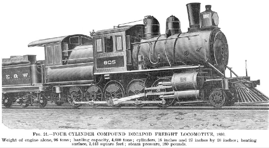
The cylinders are arranged in pairs, the piston rods engaging a common crosshead. The cylinders are 16 in. and 27 in. in diameter by 28 in. stroke. The engine alone weighs 96 tons and has a hauling capacity of 4,600 tons on a level. It is worth while to compare this with the load drawn by the first Baldwin engine, Fig. 10.
It may be remarked that engineers are much at variance on the question of compound locomotives; many men of the highest standing, while admitting that a certain success has been attained by compound engines, maintain that the economy in fuel is counterbalanced by the disadvantages inherent to the greater complication of machinery and by the extra cost for repairs. Notwithstanding this, it seems probable that the compound engine is the locomotive of the future, and that of the two cylinder type, as being the least complicated and costly.
The writer takes pleasure in thanking Mr. J. Elfreth Watkins, curator of the National Museum, Washington; Mr. Theo. N. Ely, chief of motive power of the Pennsylvania Railroad; Mr. R. S. Hughes, president of the Rogers Locomotive Company; Mr. William Buchanan, chief of motive power of the New York Central and Hudson River Railroad; the Baldwin Locomotive Works; the Westinghouse Air Brake Company; Mr. M. N. Forney, M.E.; and Mr. Clement E. Stretton, C.E., of Leicester, England, for the valuable data and drawings they have kindly placed at his disposal.
Return
to the Steam Engine Development Page
About
The Hopkin Thomas Project
Rev. April 2020