A HISTORY OF
THE
AMERICAN
LOCOMOTIVE
ITS DEVELOPMENT: 1830-1880
JOHN H. WHITE, Jr.
Dover Publications. Inc.
New York
Copyright 1968 by The Johns Hopkins Press.
This Dover edition, first published in 1979, is an
unabridged, slightly corrected republication of the work originally published
in 1968 under the title American Locomotives: An Engineering History, 1830 1880, by The Johns Hopkins Press, Baltimore. It
appears by special arrangement with The Johns Hopkins Press.
Ed. An excellent technical review of early engines - a valued addition to
any collection. Copied hereafter
are sections dealing with locomotives built during Hopkin Thomas' time; Garrett
& Eastwick, the Nonpariel, anthracite coal
utilization, chilled cast iron wheel construction, and drawings of
selected engines of the time. [J.
McV.]
The 0-4-0, 0-6-0, and 0-8-0
Locomotives
Grate Area And Heating Surface
Locomotive Types and Wheel Arrangements
THE 4 –
4 – 0
pp. 46 - 57
The 4-4-0,
variously called the American type or the standard eight-wheel engine, was the
most popular wheel arrangement in nineteenth-century America.9 It succeeded because it met every
requirement of early United States railroads. It was well suited to al1
service, including passenger, freight, and switching. It was flexible, having
three-point suspension and a leading truck, and it operated wel1 on uneven
tracks. It was simple, having relatively few parts, which made it easy to
repair. It was low in first cost, and it was relatively powerful because of its
four connected driving wheels. Finally, it was the national engine, a machine without
peer in this country, because it answered every need.
The 4-4-0 was originated by Henry R. Campbell, a
native of Philadelphia and long-time associate of M. W. Baldwin, while he was
chief engineer of the Philadelphia, Germantown, and Norristown Railway.
Campbell secured a patent on February 5, 1836, and began work on his engine a
month later. The machine was built in Philadelphia at James Brook's shop. When
finished in May, 1837, it was a giant for the times as indicated by the
following dimensions:10
|
Cylinders |
14" by 16" |
|
Wheels |
54" in diameter |
|
Weight |
12 tons (long tons) |
|
Heating surface |
723 sq. ft. |
|
Steam pressure |
90 lbs. |
It was estimated that at about 15 miles per hour
the engine could pull a 450 ton train on level ground. This represented a 63
per cent gain in tractive force over the standard Baldwin 4 2-0. Campbel1 had
succeeded in producing a machine with increased power over the six wheeler, but
otherwise the engine was not successful. Its suspension was too rigid and it
was prone to derail.11
A contemporary engraving of Campbell's
eight-wheel engine was printed in the American Railroad Journal for July 30,
1836. This cut was undoubtedly reproduced from a large engraving issued at the
time by Campbel1 to advertise his patent (see Fig. 19).
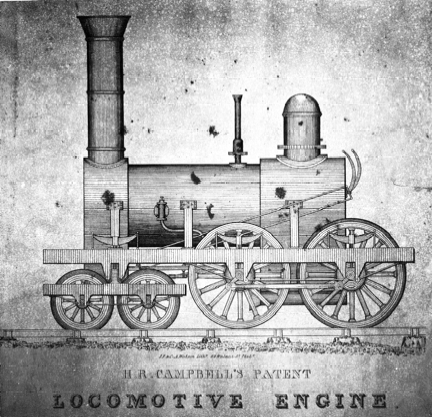
Fig 19. Campbell's
patented eight-wheel locomotive. A machine similar to the one in this
illustration was built in 1836 or 1837; it was the first 4~4~0 constructed.
A limited amount of evidence has been uncovered
indicating that Campbel1 sought to enforce his patent. He threatened to
prosecute Garrett and Eastwick for infringement in 1837.12 Several years later the minute books of the
Philadelphia and Reading Railroad refer to a dispute with H. R. Campbell for
the unlicensed use of his patent for several new eight-wheel engines built by
the Locks and Canals machine shop.l3 Settlement was made for forty shares of Reading
stock. Baldwin was reported to have purchased the right to use Campbell's
patent in 1845.14
The extent of Campbell's success in capitalizing on his patent is unknown, but
even the collection of a trifling fee for each engine built on this plan would
have resulted in a fortune for the patentee, considering the popularity of the
4-4-0 during the life of the patent.
At about the same time that Campbell was testing
his first engine, two other Philadelphians, Eastwick and Harrison, built an
eight-wheel engine named the Hercules. Completed early in 1837 for the Beaver Meadow
Railroad, it was surely the second 4-4 0 built. Little is known of its
mechanical particulars except that it weighed 15 tons. It had a flexible
running gear and, unlike Campbell's engine, could adapt itself to uneven,
tracks. The Hercules was fitted with a separate "truck frame, after a design of Eastwick (see figure
below), which equalized two driving axles. Eastwick's equalizer was not
entirely satisfactory and was succeeded a year later by Harrison's equalizing
lever. The equalizing lever, which allowed three-point suspension, was possibly
the most important American contribution to locomotive design. More will be
said on this subject in section on suspension.
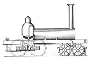
Andrew Eastwick's patent
of 1837 was devised to improve the suspension of the new 4-4-0 locomotive. The
design was not successful, however, and was superseded by Harrison's plan.
Eastwick's and Harrison's perfection of the 4-4
0 did immediately bring a general adoption of this style of engine For the next
two years they were the only builders to offer 4-4-0's. Norris, probably the
next builder to produce eight wheelers, built his first in 1839. Rogers, Locks
and Canals, and Newcastle followed, building their first 4-4-0's in 1840.15 Even so, production was
limited; only about twenty 4-4-0s were in service by 1840.
After 1840 the production of 4-4-0's increased
sharply. The eight wheeler had proved itself a practical road engine with
greater capacity than the 4-2-0 and was readily accepted as the new national
type. Even Baldwin, a dedicated advocate of the 4-2-0, was finally forced in
1845 to build eight wheelers since few roads were purchasing six-wheel engines.
The typical 4-4-0 of the early 1840s was a
compact little machine of short wheel base which rarely weighed more than 12
tons. Such a machine is illustrated by the Rogers engine apparently built for
the Utica and Syracuse Railway, in Fig. 20. Another example is the Gowan and
Marx discussed at some length
later in this study. Nearly all of these early 4-4-0's were characterized by
the connection of the main rod to rear driving wheels.
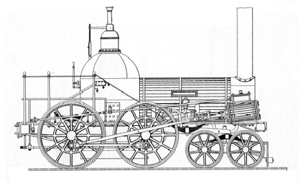
Fig. 20. A Roger's 4-4-0
of about 1843. Wheels, 60 in.; cylinders, 12 in. by 18 in.; weight, 11 tons.
The 4-4-0 took on a more familiar appearance in
the 1840's when the lengthened boiler resulted in the wider separation of the
truck and drivers. The cylinders were now so far from the rear drivers that the
main rod was commonly attached to the front drivers. Many significant changes
in general arrangement occurred during the mid-1840's; it is unfortunate that
no complete working drawings for any 4-4-0 of this period are known to exist.
There are, however, several fragmentary drawings for eight wheelers of this
period that worthy of consideration.
The earliest of these drawings, reproduced in
Fig. 21, is the Massachusetts and the Connecticut. Built in October, 18 by
Rogers, these engines are typical 4-4-0's of the period The drawing traced from
an original Rogers order book is regrettably sketchy. The other three drawings
of 4-4-0's of the 1840s, Figs. 22-24, while more complete, show more atypical
designs. The Wm. H. Watson (Fig. 22) was an unusually large locomotive for its
time, weighing nearly 27 tons, and embodied several unusual, though not
freakish, design features. The engine was built in the Baltimore shops of the
Baltimore and Susquehanna Railroad to the design of James Millholland.
completed in March, 1847, it was used for heavy freight service. The inside
cylinders were not unusual, but the massive cast-iron crank axle was a feature
decidedly peculiar to Millholland. The cylinders measured 18 inches by 18
inches; here again the fact that the stroke was equal to the diameter of the
cylinder was at variance with usual practice. The truck was also unusual since the
frame was outside the wheels and below the axles. The uooden outside frame was
rather antique for the period.
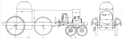
Fig. 21 The Massachusetts and the Connecticut,
built in 1846 by Rogers. and data copied from an original Rogers order
specification. Weight 18 tons.
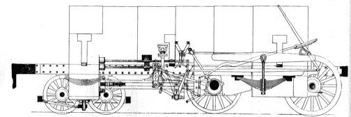
Fig. 22. The Wm. H.
Watson, built in 1847 by James Millholland in the Baltimore and Susquehanna
Railroad shops.
The Mohawk (see Fig. 23), while more conventional
than the Watson, was also quite a large machine even for the late 1840's. It
weighed 22 tons and had 15-inch by 25-inch cylinders and 60-inch wheels. The
Practical Mechanics Journal for January, 1850, noted that the engine was
rebuilt by Walter McQueen in the Albany and Schenectady Railroad shops. The
rebuilding apparently took place in 1847 or 1848, but no evidence is available
on the original builder nor on the exact nature of McQueen's alterations. The
Mohawk had one remarkable design feature, the cylinder saddle, which generally
is not credited until the early 1850's.
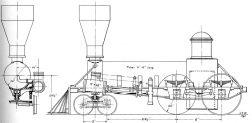
Fig. 23. The Mohawk of
the Albany and Schenectady Railroad as rebuilt by Walter McQueen in the company
shops in 1847 or 1848.
The final 4-4-0 of this group is the Tioga (Fig. 24) built by Baldwin
for the New York and Erie in December, 1848. It was a six-foot-gauge engine and
was therefore large for the period. It weighed slightly over 28 tons and had
cylinders 16-1/2 inches by 20 inches with 72-inch drivers. Except for its size
it is probably a fair representative of Baldwin's standard practice of the late
1840's. The outside frame (note the heavy cast-iron pedestals) was not used
much in this country. The outside cranks (see Fig. 25) were necessary because
of the outside frame. Other mechanisms worthy of note are the double throttle
valves, the forward steam dome, and the separate cutoff. Baldwin built eight
engines on this plan for the Erie Railway between December, 1848, and June,
1849. They were among the last half-crank engines built by Baldwin.
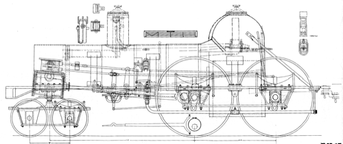
Fig. 24. The Tioga,
built by Baldwin for the New York and Erie Railway in 1848. Six-foot gauge.
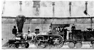
Fig. 25. The New York
and Erie's No. T, 13, built in 1848 by Swinburne. Shown as rebuilt with a
spread truck, link motion, and other minor modifications. Note the similarity
of this engine and the Tioga.
Generally, the development of the 4-4-0 between
1840 and 1850 was simply an enlargement of the machine as it was first
introduced. Boilers were set low, conforming to a near panic about high centers
of gravity, short wheel base trucks prevailed, and the Bury firebox and
hook-motion valve gears were standard. All of this was changed in the early
1850's. A "modern" machine emerged that revolutionized the industry
It combined several notable features such as spread leading trucks, Stephenson
link motion, and the wagon-top boiler.
Zerah Colburn, writing in 1860, believed that Thomas Rogers deserved
credit for the combination, though not for the invention of these features:
"Thomas Rogers . .
. may be fairly said to have done more for the modern American locomotive than
any of his contemporaries. In America the standard wood-burning engine of today
stands precisely where he had brought it in 1852, and where he left it at his
death in 1856."16
While not wishing to detract deserved praise
from Rogers, it should be noted that William S. Hudson became superintendent of
the Rogers works precisely when the first modern engines were built, in 1852.
In addition, in 1852 William Swinburrne, also from Paterson and formerly with
Rogers, built a locomotive named America that combined all the reforms credited
to Rogers. The question, then, is who was responsible for these
reforms—the proprietor, the superintendent, or some obscure draftsman?
Credit properly given or not, Rogers' new style of engine was rapidly adopted
so that by 1855 every progressive American builder was producing engines on the
"Rogers pattern." This pattern was little changed, except by an
increase in size, for the next 30 years. The New Jersey (Fig. 28) clearly
illustrates the "modern" style of eight wheeler introduced by Rogers
in 1852. The lithograph from which this illustration is taken is undated.
Rogers is known to have built four engines named New Jersey between 1852 and
1854. However, none of these had u heels as large as those indicated by the
lithograph.
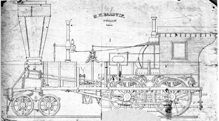
Fig. 26 A Baldwin 4-4-0 of about 1848
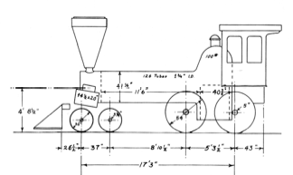
Fig. 27. The Allegheny,
built by Baldwin for the Pennsylvania Railroad in 1850.
The American type continued unrivaled as a
general service engine through succeeding decades. Angus Sinclair claims it
reached its peak of popularity in 1870 when 85 per cent of the engines in
service were of this type.17 Sinclair's estimate might be somewhat
exaggerated, yet in 1872 4-4-0's accounted for 60 per cent of the Baldwin
work's production. The Master Mechanics Association concluded after comparing
all wheel arrangements that "the eight wheel engines do the same work at a
much less cost.'' 18
In the same report Wilson Eddy, master mechanic of the Boston and Albany,
attacked the "Mogul" and “Consolidation,'' saying, "They run
much harder, and with much more friction and more wear and tear of the track
than a common eight wheel engine."19 Eddy supported his contention in 1876 by
testing one of his remarkable eight wheelers known as "Eddy Clocks"
against a Rhode Island Mogul named the Brown.20 Except for wheel
arrangement the two engines were nearly identical in size, but the Adirondack,
Eddy's engine, had a firebox 6-1/2 inches wider than its rival because of Eddy's
clever use of a slate rail frame. The results of the test were a decided
triumph for the Adirondack which consumed $190 less fuel while doing the same
work as the Brown. Eddy's point was that a good American could do anything a
Mogul could, and do it cheaper! The actual point was that in the 1870's more
roads were finding the American too small for freight service.
The decline of the American type was rapid by
the mid 1880's. This is most noticeable in the decreasing number of new 4-4-0's
built. In 1884, 60 per cent of the new engines purchased were 4-4-0's.21 Two years later only
half of new construction was of this type, and by 1891 just over 14 percent was
of the American tvpe.22 The eight wheeler maintained its popularity for
passenger work into the early 1890's until heavy wooden vestibule coaches and
faster schedules proved too much for its limited capacity. By 1900 the 4-4-0
was an obsolete design. It continued to be built in very limited numbers as
late as 1945 when Baldwin turned out a tiny 33-ton 4-4-0 for the United of
Yucatan Railways.
It would be difficult to exaggerate the
importance of this single class of locomotive to the nineteenth-century
American railway. No other style of general purpose locomotive enjoyed a
greater popularity, and few proved as useful or satisfactory in performing the
work they were required to do.
9 The class name "American" was suggested for the 4-4-0 in the Railroad Gazette, April 27, 1872, p. 183. This is the earliest recorded instance of the term known to the author.
10 American Railroad Journal July 30, 1836, pp. 465-66; see also Railway and Locomotive Historical Society Bulletin, No. 35, for P Warner's excellent general history of the 4 4-0 locomotive.
11 Campbell's first 4-4-0 was later sold to the Long Island Railroad, according to a note in C. B. Stuart's Civil and Military Engineers (New York, 1871), p. 330. This is confirmed in part by a note in the Railway and Locomotive Historical Society Bulletin, No. 10 (p 12), which stated that a 4-4 0 named Chichester was acquired by the Long Island from H. R. Campbell in 1842. It is also claimed that the above locomotive was a Baldwin 4 2-0 rebuilt by Campbell.
12 American Railroad Journal, August 26, 1837, p. 534.
13 Minutes of the Philadelphia and Reading Railroad, January 21, 1843, in the files of the Reading G., Philadelphia, Pa.
14 The History of the Baldwin Locomotive Works (Philadelphia, 1923), p. 41.
15 M. N. Forney in his history of the Rogers Locomotive Works Locomotives and Locomotive Building (orig. pub. New York, 1886, 2nd ed., Berkeley, Calif., 1964), p. I7, incorrectly states that Rogers built his first 4-4-0 in 1844. This error has been repeated many times. Rogers built nearly twenty 4-4-0's between 1840 and 1844. The Oneida of the Syracuse and Utica Railroad, completed in June 1840, was probably his first.
16 Clark and Colburn, Recent Practice, p. 48. In its issue of October 20, 1855, the Railroad Advocate credited Rogers with the most advanced design
17 Sinclair, Locomotive Engine, p. 636.
18 American Railway Master Mechanics Association Annual Report, 1872, p. 171; hereafter cited as Master Mechanics Report.
19 Ibid., p. 130. 20 Ibid., p. 177.
21 National Car and Locomotive Builder, March, 1884, p. 30
22 Ibid., January, 1887, p. 12, and January, 1892, p. 10.
23 G. E. Sellers, "Early Engineering Reminiscences," American Machinist, September 12, 1885, p. 5.
THE 0-4-0, 0-6-0, AND
0-8-0
pp. 66 - 69
The four-wheel connected engine is the most
elementary wheel arrangement possible. Its history as a road engine is
extremely brief and accordingly will be treated briefly. Several of the British
imports, notably Stephenson's "Sampson" class, a few early American
products such as the West Point and De Witt Clinton, and the Baltimore and
Ohio's Grasshoppers were all intended for road service. Their limited power and
poor tracking soon reduced the 0-4-0 to switching service, however, after which
it played a minor role in locomotive development.
What would have been the first American 0-6-0
was ordered from Stephenson by the Baltimore and Ohio in 1829, but the machine
was not delivered, because it was lost at sea.35 The Nonpareil, built by
the Beaver Meadow Railroad in 1837 or 1838, was probably the first 0-6-0 constructed
in this country. Baldwin's
first flexible-beam truck engines, introduced in 1842, were 0-6-0's. They were
probably the most numerous machines of this wheel arrangement in the United
States during the early years of the 0-6-0's development. Between 1842 and
about 1864 some 200 were manufactured. Norris also produced six-wheel connected
engines; they built a number of 0-6-0's from the early 1840's through the
1850's. The Philadelphia (see below) is an example of a Norris six wheeler. A
number of powerful six-wheel freight engines were built between 1854 and 1856
by Rogers for the Buffalo and Erie, the Buffalo and State Line, and the
Lackawanna railroads. A lithograph was issued of one of these engines, the Volcano. This engine weighed 23
tons and had 16-inch by 22-inch cylinders and 54-inch drivers. The New Jersey
Locomotive and Machine Works and Danforth-Cooke also built engines (mainly for
the Lackawanna) on the same plan during the mid-1850's All 0-6-0's were
intended for slow freight traffic and were a minor wheel type on early American
railroads. Before 1870 is questionable if more than 300 were constructed in
this country. During the 1860's and 1870's they were entirely replaced by 2~0's
or 2-8-0's for road service and after that date were used only for switching.
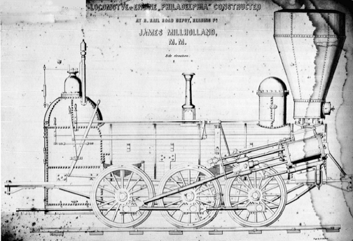
The Philadelphia, shown
as remodeled by Millholland in 1848 or 1849.
The first eight-wheel connected engine was, like
the 0-6-0, built at an early date. The Camden and Amboy Railroad built an
eight-wheel engine, the Monster, between 1835 and 1838.36
An awkward machine, it seemed to favor marine
rather than railway engineering practices. It was not truly an 0-8-0, for spur
gears rather than connecting rods were used to couple the second and third
driving axle. The machine was indeed monster; it weighed about 18 tons and had
cylinders 18 inch by 30 inches. Four heavier engines were built on this design
in 1852 and 1854 for the Camden and Amboy by the Trenton Locomotive Works.
Another was built by the Camden and Amboy in 1852, thus making a total of six
"monsters."
Ross Winans designed the next 0-8-0 in this
country after the original Monster. The American Railroad Journal of March 15,
1841, describes this engine as weighing 19-1/2 tons with cylinders 14-1/4
inches by 24 inches. The machine was apparently new at the time and was
undergoing tests on the Baltimore and Ohio. In September, 1841, the Western
Railroad (Massachusetts) purchased this or an identical engine from Winans and
named it the Maryland. The Maryland had a vertical boiler and spur gear drive
and was in general arrangement an enlargement of Winans' earlier
"Crab" engines. Winans and Baldwin each built three more eight-wheel
engines of this design in 184142. The Western Railroad found them
unsatisfactory and all were retired by about 1850.
The Baltimore and Ohio found the 0-8-0 well
suited to its heavy coal traffic and became the largest single user of eight
wheel connected engines in the nineteenth century. Between 1844 and 1846 the
road received twelve locomotives from Winans, which, except for horizontal
boilers, were identical to those of the Western Railroad. These curious
machines became known as "Mud Diggers." A thirteenth "Mud
Digger" was built in the company's shop in 1847. In 1847 Winans materially
improved his eight-wheel engines by eliminating the gear drive and making a
direct connection to the driving wheels. Four machines were built on this
reformed plan for the Reading in 1847.
The following year the Baltimore and Ohio
purchased Winans' first "Camel" locomotive. This machine was the
primogenitor of the most famous class of 0 8-0's built in this country.
Designed for coal-burning and heavy traffic, some two or three hundred were
used successfully by several roads, despite several design defects. The Camel's
history is more fully discussed later.
In addition to Winans products, the Baltimore
and Ohio built and purchased 0-8-0's from other builders. An example of one of
the company-built eight wheelers is the unidentified machine shown in Fig. 34.
Note the similarity of this drawing to the Hero (Fig. 35), designed by Thatcher
Perkins in 1848. In 1865 Perkins designed an improved 0 8-0 that was intended
to supplement the Baltimore and Ohio's aging fleet of Camels. Twenty-four
Perkins 0-8-0's were built. They represent the final example of this wheel
arrangement designed for road service.
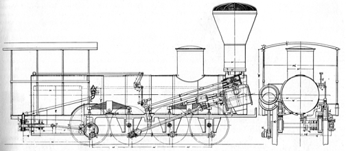
Fig. 34. An eight-wheel
connected locomotive of the Baltimore and Ohio Railroad. An exact
identification cannot be made (it may be only a design study), but its date of about
1848 is certain.
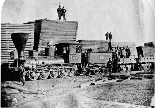
Fig. 35. The Baltimore
and Ohio's Hero, built by Thatcher Perkins at the company shops in 1848. This
photograph was taken in 1867. The engine was rebuilt in 1857, but the exact
alterations made are not known.
Aside from the Baltimore and Ohio and Winans,
Baldwin was the only other major figure associated with the 0-8-0. In 1846 he
built his first 0-8-0, which, like the 0-6-0, was a flexible-beam truck engine.
Subsequently, Baldwin built about three hundred 0-8-0's, ending production of
this design in 1866.
At best, six or seven hundred eight-wheel
connected engines were constructed in this country before 1870. Their use was
restricted to a few roads and their part in the early development of American
locomotives was accordingly minor.
35 C. F. D. Marshall, A History of the Railway Locomotive Engine Down to the Year 1831 (London, 1953), p. 145.
36 In his report of 1838 J. Knight described the Monster as nearly completed.
FUEL
pp. 86 - 90
COAL-BURNING
Compared to coal, wood is a bulky, primitive
fuel with a low calorific value. In the nineteenth century one ton of soft coal
was considered equal to 13/4 cords of wood, or, roughly figuring wood at 3,000
pounds per cord, 2,000 pounds of coal equaled 5,250 pounds of wood.l9 While these figures are
not exact, the greater heating value of coal over wood was well understood by
engineers at the beginning of the railroad era. Contrary to present erroneous
beliefs that wood was the only fuel considered at the time, a surprising number
of our first railways initially experimented with coal-burning locomotives,
turning to wood only as a last resort. In 1828 the Delaware and Hudson planned
to use coal-burning engines for two reasons: one, it was a coal carrier; two,
the several locomotives imported for that service—the Stourbridge
Lion among them— were
copied from British colliery locomotives, which had always burned coal. The
failure of this pioneering steam railroad venture was attributable to weak
tracks rather than to the use of coal as fuel. The Baltimore and Ohio's first
experimental locomotive, the Tom Thumb, burned anthracite successfully; the
road then specified that all engines entering its 1831 locomotive contest must
use the same fuel. In later years this road was a leader in the development and
use of coal-burning locomotives. S. H. Long, the renowned civil engineer and
bridge designer, built a number of anthracite-burning locomotives in the early
1830's. His locomotives were tested on the Philadelphia and Columbia, the
Newcastle and Frenchtown, and the Boston and Providence Railroads. All were
unique and highly individual mechanisms, but none was considered a success.20 Another engineer
usually remembered for his civil-engineering contributions, John B. Jervis, a
contemporary of S. H. Long, conducted some experiments with coal-burning
locomotives on the Mohawk and Hudson Railroad. Jervis carried over this idea
from his previous employer, the Delaware and Hudson Canal Company. The De Witt
Clinton, before entering regular service, was fired with "Lackawanna
Coal" in July, 183l.21 The test, though unsuccessful, did not
discourage Jervis from having another hard-coal burner constructed a year
later. This engine, the Experiment, worked no better than the De Wit Clinton
and was soon fitted with a wood-burning firebox. The Camden and Amboy Railroad
is also known to have been a early investigator of coal-burning engines. A good
deal of th interest is attributable to members of the Stevens family of
Hoboken, New Jersey, who were not only chief promoters of the railroad but also
early advocates of coal-burning steam ships. The road may have experimented
with coal-burning as early as 1833, as indicated by the wide firebox boiler
engine, but it is definitely known that the eight-wheel freight locomotive the
Monster, built between 1836 and 1838 at the company shops, was intended for
coal-burning.22
The road did not make a wholesale conversion to coal as a result of this
experiment, but other hard-coal engines were placed on the road in the late 1840's.
Of the several early attempts at coal-burning,
only two small anthracite roads in Pennsylvania, the Beaver Meadow and the
Hazleton, completely rejected wood. Both lines ran slow coal trains with
continuous runs of only 14 miles; thus there was an opportunity to rekindle and
otherwise nurse the engines along. Of course, this restricted manner of
operation was not practical for an ordinary railroad where passenger and
merchandise trains could not be expected to put up with delays occasioned by a
dull fire.23
Obviously the early attempts to introduce
coal-burning locomotives were a failure. A small number of "coalers"
continued to work, but, in general, early American roads were powered almost
exclusively by wood-burners. The chief difficulty was an inability to burn
coal. The blame for this falls directly on the type of coal available. Only
anthracite, or as it was first known, "stone coal," was mined in this
country before about 1840. It was a difficult fuel to burn, particularly in the
small locomotive fireboxes of that time. In addition, it was a slow-burning
fuel and was therefore particularly unsuited to the needs of the locomotive,
where rapid combustion was essential for a rapid production of steam. Had soft
coal been more commonly available in the 1830's, it is likely that successful
coal-burners would have been developed many years earlier.
The high price and limited supply of coal in
this period were other factors that discouraged an early introduction of coal
burning locomotives. Coal cost from $7.00 to $10.00 per ton in the 1830's.24 The big mines were
located in eastern and central Pennsylvania. Transportation costs considerably
boosted the price per ton for roads outside this area. As other coal fields
opened, particularly the Maryland, West Virginia, and southern Illinois
deposits, railroads in these areas were encouraged to adopt coal. But few of
these fields were in production before 1850; some were not in full operation
until many years later. Anthracite fields, which had been commercially worked
before any locomotives were employed in this country, did not achieve large
production until after 1840. Only after that time did coal become an important
American fuel.25
Industry, in general, was slow to adopt coal; thus, railroads were not alone in
their slow acceptance of this fuel.26 As production in the old fields grew, new
fields opened, and railroads could reach the mines and offer cheap
transportation; coal prices accordingly showed a steady decline as the
nineteenth century passed. By the mid-1850's coal was down to about $3.00 per
ton, and in 1862 the Baltimore and Ohio was able to get coal at 75 cents a ton
because of the many mines along its route. It was this decline in coal prices,
rather than the dramatic increase in wood prices, that brought about the great
conversion in locomotive fuel.
To return to examples of railroads making early
use of coal for locomotive fuel, no such account would be complete without reference
to the Baltimore and Ohio Railroad. This company showed a strong interest in
coal burning from its earliest years and was the only major American line to
operate coal burning locomotives continuously in the last century. Following
the first experimental locomotives in 1831, a class of coal-burning engines
with vertical boilers was perfected for freight service. In later years the
road continued to build or purchase new designs of coal-burning freight engines
but turned to woodburners for passenger service in the mid-1830's. Before 1840
anthracite was imported from Pennsylvania at $8.00 a ton.27 After the road reached
the soft-coal fields of western Maryland in 1840, bituminous coal was adopted.
In the next year, half of the road's power burned coal exclusively while a few
engines burned a mixture of wood and coal. A large number of eight-wheel,
coal-burning freight locomotives were purchased during the next several years.
Passenger trains were handled by wood-burners until the mid-1850's when new tests
were made with coke and coal. In 1858, 14 of 34 passenger engines were
converted to coal or coke. By November, 1859, all 235 locomotives were
coal-burning except for one freight engine and ten old light machines.28
The Philadelphia and Reading was another road
obviously interested in coal-burning locomotives because of the immense coal
traffic passing over its line. The original minutes of the Board of Managers
revealed the earnest desire of the Reading's management to adopt coal as
expressed in the following resolution dated April 13, 1835: "Resolved that
this board deem it of the utmost importance that the locomotive engines to be
constructed for this Company be built with a view to the exclusive use of
anthracite as fuel." The road's third locomotive, the Delaware, delivered
by Winans in 1837, was a coal-burner but it was not a success and was abandoned
in 1845. The Gowan and Marx, also intended for hard coal, was converted to a
wood-burner not long after entering service in 1839. Discouraged by these and
undoubtedly other unrecorded failures, the Reading abandoned further attempts
at coal-burning until 1847. In that year a mechanical monstrosity named the
Novelty was built in the company shops after a patented design of G. A.
Nicolls. The boiler was carried on a separate eight-wheel car; the flexible
pipe necessary for carrying steam to the locomotive leaked. This and other
complex auxiliary apparatus were devised by Nicolls. Predictably the engine was
a failure. In the same year Winans delivered several eight-wheel connected
engines of a more conventional design, but they were not notable successes.
This slow beginning was carried forward by James Millholland, who after an
unpromising series of experiments perfected a practical anthracite firebox by 1856.
By 1859 the road was virtually all coal-burning.
In New England, as already indicated, slower
progress was made. The great distance from the coal fields kept prices high.
Coupled with this was the resistance of many old-line managers to innovations.
One exception to this trend was George S. Griggs, master mechanic of the Boston
and Providence Railroad. Griggs was associated with the road when S. H. Long's
anthracite engines were purchased in the 1830's. While these engines failed as
coal-burners, Griggs was not prejudiced by. their poor performance. In 1856 and
1857 he initiated new tests and in the process developed the brick arch and
diamond stack, both of which were important contributions to coal burning. By
1860 the road was said to be powered almost entirely by coalburners.29 This statement was
somewhat premature, for, according to the road's annual reports, wood-burners
were in service as late as 1874 or 1875.
In the Middle Atlantic states the Philadelphia,
Wilmington and Baltimore Railroad was an early convert to coal-burning. In 1841
soft coal was used but it was abandoned after only six months.30 When interest in
coal-burning was revived, the road made the mistake of turning to freak firebox
designs. In 1856 a Taunton-built engine, the Essex, with a Dimpfel boiler, was
placed in service. This machine and the several that followed were only
moderately successful. Conventional coal-burning engines were acquired and by
1862 the road's annual report. stated: "Coal burning in locomotives is no
longer an expert meet, but a well established fact and a decided economy."
Three years later all but seven main-line engines were fueled with coal.31
The fuel question followed a similar pattern in
the Midwest. The Chicago, Burlington and Quincy was one of the first midwestern
railroads to convert. It acquired its first coal-burner in 1855 after reaching
the southern Illinois coal fields. The next year, eleven coal engines were in
service; in 1859 twenty-five were on the road. The conversion was accelerated
by the purchase of coal mines so that by 1868 all of its engines were burning
coal. The Illinois Central began experiments with coal-burning locomotives in
1855. At first, poor local coal dampened prospects for an early conversion,
but, despite this difficulty, over half of the road's engines were coal-burners
by 1861. Five years later only 5 of 151 engines were wood-burners. Not all
railroads in this area found native coal satisfactory, and the Galena and
Chicago Union's report of 1863, while admitting that wood prices were
prohibitive, stated that coal was no ready solution.
Illinois coal was inferior because it contained
a high percentage of sulphur. Until more precise methods of processing were
developed, eastern coal was imported. In later years Illinois coal was
successfully employed, despite early complaints regarding its quality, and
western roads kept pace with the other major lines in abandoning wood.
The conversion of locomotive fuel from wood to
coal may be summarized as follows: The early interest in coal-burning resulted
in no substantial use; only a few coal-field lines regularly employed this
fuel. By the 1850's a renewed and substantial interest in coal-burning was
thwarted by the mistaken belief that revolutionary changes in firebox design were
necessary. It was quickly established that fireboxes of ordinary construction
were capable of successful coal-burning, and by the late 1850's several
important railroads had adopted coal. During the 1860's and 1870's coal was
accepted as the best fuel for locomotives, and all major railroads began
abandoning wood. By 1880 more than 90 per cent of railway fuel was coal.32
During the next two decades all American
railroads, except for a few obscure lines, converted to coal.
Compared to coal and wood, the other fuels
considered for locomotive use are of only passing importance. Coke was the most
important alternate tested, but its use was extremely limited. As late as 1850
an English technical writer observing American practice stated: "The use
of coke is nowhere resorted to. Its expense would make it inadmissible; and in
a country so thinly inhabited, the smoke proceeding from coal or wood is not
objected to."33
From this comment it can be understood that coke was the required fuel in
England because of the smoke nuisance of coal and wood. Coal was adopted in
that country during the period that American railroads changed from wood to
coal. To turn to the use of coke in the United States, one of the few lines to
use the fuel was the Baltimore and Ohio Railroad. In 1854 two passenger
locomotives were tested with coke; the results were encouraging for, although
it was more expensive than "raw coal," no sooty smoke was given off.34 The road's 1857 report
noted the construction of six new coke-burning passenger engines. The greater
cost of coke ($2.00 per ton compared to 75 cents for a ton of coal) discouraged
continuance of coke-burning locomotives after about 1862. While coke was for a
short time considered ideal for passenger service because of its clean burning,
it was soon discovered that careful firing of coal could eliminate a good
portion of the smoke. To encourage this practice the Illinois Central placed
the following notice in the cabs of its passenger locomotives.35
Machinery
Department, Illinois Central Railroad.
Weldon,
May 7th, 1868.
SPECIAL
INSTRUCTIONS TO PASSENGER ENGINEERS.
To prevent
your engine throwing out large quantities of smoke, you will see that your
fireman is very particular in the manner of firing, and that he observes
closely the following rules:
Do not throw more than
two shovels of coal at one time, and scatter it well over the grates.
Keep the fire as nearby
uniform as possible.
Keep the coal in your
tender dampened, so that the dust from it will not be blown back upon the train.
Whenever the steam is shut off, the blower should be used lightly.
The air openings around
the furnace and in the door should be kept open as much as possible.
Much of the annoyance
from smoke and coal dust will be prevented and a large saving in fuel effected
by attention to the above rules.
S. J. HAYES
Superintendent of
Machinery.
Petroleum was considered as a fuel surprisingly
early, but its short supply and high price prevented any extensive use in this
country during the nineteenth century. As early as 1864 the United States Navy
experimented with oil-fired boilers, and suggestions were made at the time for
oil as a locomotive fuel.36 Ten years later an old engine of the Boston and
Providence was altered to burn coal oil, but the experiment ended in failure
after a twenty mile run when oil leaks set the engine on fire.37 The first regular use of petroleum for
locomotive fuel developed in Russia. Thomas Urquhart, superintendent of the
Grazi Tsaritzin Railway, began the use of fuel oil in 1882; by 1885, 143
engines on the line were using this fuel.33
There was, however, little interest in oil-fire locomotives in the United
States until the great western oil fields produced large surpluses during the
early 1900's.
17 Master Mechanics Report, 1872, p. 49.
18 Railway and Locomotive Historical Society, Special Bulletin, "Vermont Central," 1942.
19 Colburn and Holley, The Permanent Way, p. 8. Marks's Mechanical Engineers Handbook, pp. 711 and 799, shows 1 pound coal = 13,000 B.T.U..; 1 pound wood = 5,800 B.T.U. R. H. Thurston's A Manual of Steam Boilers (New York, 1896), p. 160, offered a different ratio, stating that 1 cord of well-seasoned yellow pine equaled only 1/2 ton of good coal.
20 Colonel Long's attempts at locomotive building are covered in Railway and Locomotive Historical Society Bulletin, Nos. 79 and 101. Between 1826 and 1833 Long secured several patents for locomotive boilers and running gears.
21 W, H. Brown, The History of the First Locomotive in America (rev. ed.; New York, 1874), p. 178, reproduced a notice from the Albany Argus, July 25, 1831.
22 Master Mechanics Report, 1885.
23 Reports on the Beaver Meadow and Hazleton coal-burning locomotives appear in the Journal of the Franklin Institute, June, 1847, and in G. W. Whistler, Jr.'s Report upon the Use of Anthracite Coal in Locomotive Engines on the Reading Rail Road (Baltimore 1849), pp. 27-28.
24 Knight and Latrobe, Locomotive Engines, note coal prices at this rate on several eastern roads.
25 H. N. Eavenson, First Century and a Quarter of the American Coal Industry (Pittsburgh, 1942).
26 The iron industry showed little interest in replacing charcoal with coke until after 1850; the slow conversion of western riverboats to coal is discussed in Louis C. Hunter's Steamboats on the Western Rivers. One of the few important industries to make an early conversion to coal was Hudson River and ocean steamers.
27 Whistler, Anthracite Coal, p. 21.
28 Letter of Henry Tyson to J. W. Garrett (president, Baltimore and Ohio Railroad), November 9, 1859.
29 American Railway Times, January 28, 1860.
30 American Railway Times, March 9, 1861.
31 For more data on the Philadelphia, Wilmington and Baltimore's conversion to coal-burning, see Railway and Locomotive Historical Society Bulletin, No. 21.
32 The 1880 census lists fuel consumed by individual lines but gives totals for major geographic sections only. The author's totals are 1,388,723 cords of wood; 9,531,080 tons of coal; ninety per cent is en approximate percentage based on 1 ton's equaling 1-1/2 cords.
33 Dionysius Lardner, Railway Economy (New York and London, 1850), p. 336.
34 Mendes Cohen, Report on Coke and Coal Used with Passenger Trains, on the Baltimore and Ohio Railroad (Baltimore, 1854).
35 Locomotive Engineering, May, 1899, p. 238.
36 American Railway Times, January, 1864, p. 14. 37 Boston and Providence Annual Report, 1874. 38 Institution of Locomotive Engineers Journal, 1952, pp. 42 see also Eugene McAuliffe, Railway Fuel (New York, 1927).
COMPONENTS
BOILER TUBES
pp. 99 - 100
The boiler waist contains a large number of
small-diameter fire tubes intended to increase heating surface and promote
steam-making capacity. The tubes are parallel to one another and connect the
fire- and smoke-boxes.
The earliest American locomotive boilers
invariably contained 100~150 copper tubes varying from one and a half to one
and three-quarters inches in diameter. Copper was easy to fabricate Thin copper
sheets, generally less than one-eighth of .an inch thick, were cut into strips,
the strips were rolled and lap-welded into tubes. In about 1860 seamless copper
tubes were introduced, but lap-welded tubes continued to be manufactured for
many years. The soft metal was easily flanged and a good steam-tight joint
could be made at the tube sheets with a simple calking tool. When the joint
worked itself loose during expansion and contraction, it was readily re-flanged
and made good for many more miles of use. Copper tubes gave remarkably good
service. The Pittsburgh, Fort Wayne and Columbus Railroad reported twenty years
of service, while the Little Miami Railroad realized 150,000-200,000 miles when
copper tubes were used in wood-burning engines.l6
Brass tubes were first used in this country in
1851.17 Their use spread fairly
rapidly so that within the next four years 800 locomotives were fitted with
brass tubes.l8
Greater cost and difficulty in flanging (brass being less ductile than copper) prevented
them from superseding copper tubes in America; they were immensely popular in
Britain, however.
Iron tubes were used as early as 1831 by the
Baltimore and Ohio and were taken up at an early period by the other roads
operating coal-burning locomotives. Iron tubes were difficult to flange, but
they were considerably cheaper and more durable than copper tubes. The American
Railway Review stated that copper tubes cost $1,000 per locomotive compared to
$400 for iron tubes.19 In some cases, copper ends were welded on for
easy flanging. Iron tubes were fabricated from sheet stock and the joint was
brazed. The ability of iron to withstand the erosive action of fly ash led to
its adoption for coal-burning engines. After 1860 iron tubes were on the ascent
and the use of copper and brass became increasingly rare as the century closed.
Experiments with steel tubes began in the early
1860's. By 1863 a British supplier, Russell and Howells, could report the use
of steel tubes by several important railroads. These included the Camden and
Amboy, Erie, Hudson River, and other eastern lines.20 Despite this initial
interest, however few roads adopted steel for locomotive tubes. In 1876 it was
reported that lap-welded iron tubes were the general rule; steel tubes were not
considered to be worth the extra cost.21 As late as 1892 Meyer concurred with this
observation, stating steel was only "sometimes" used for tubes.22
Steel did not rival iron for tubes during the
nineteenth century, even though it surpassed its competitor years earlier in
boiler and firebox manufacture. It was difficult and expensive to weld. Because
it was stronger than iron, very thin steel tubes could be constructed. These
proved to be better heat exchangers because there was less wall thickness to act
as insulation. Yet the difficulties of welding and higher costs prevented the
general adoption of steel tubes until about 1900 when cheap, seamless steel
tubes were introduced.
Tube diameter remained remarkably unchanged
throughout the last century. One and three-quarter inch tubes were standard up
until 1860 when a movement began for two-inch diameters. With minor exceptions,
this size was popular th the 1890's.
16 Master Mechanics Report, 1870, p. 105; 1872, p. 148.
17 Colburn, Locomotive Engineering, p. 83.
18 Railroad Advocate, May 5, 18 5 5, p. 3.
19 American Railway Review, July 4, 1861, p. 405.
20 A circular issued by Russell and Howells, in the M. W. Baldwin Letters (Historical Society of Pennsylvania, Philadelphia, Pa.); hereafter cited as Baldwin Letters.
21 Institution of Civil Engineers, Proceedings, Vol. 5 3 (1878), p. 5 1.
22 Meyer, Modern Locomotive Construction, p. 437.
FIREBOX CONSTRUCTION
pp. 102 – 105
The major patterns of fireboxes have already
been discussed in the opening section on boilers. However, the construction and
material of this structure require further explanation. The firebox, known as
the heart of the boiler, is a box within a box. The space between the inner and
outer box is filled with water. This water space partially insulates the inner
firebox plates from the destructive action of the fire. In wood-burning engines
the water spaces were 2 inches wide or less because of the relatively low heat.
Coal-burners, developing more intense heat, were built with 3- or 31/2-inch
water spaces. The inner and outer firebox plates were held parallel by stay
bolts usually set on 5- to 6-inch centers. These bolts were threaded and
riveted at both ends for security and steam-tightness. Robert Stephenson used
this style of construction on the Rocket in 1829 and it remained in use well
into the twentieth century. Hollow stay bolts were used by F. P. Dimpfel for
stationary boilers as early as 1839.35 Their introduction to locomotive practice is
uncertain, but hollow stay bolts were recommended by the master mechanics in
their report of 1872 and were apparently in regular use before that time.
The crown sheet or top-flat plate of the firebox
required support to prevent its collapse. Flat, iron bars called crown bars
were used for this purpose. Five to twenty such bars, depending on the size of
the crown sheet, were used. They were set on edge and riveted or bolted to the
crown sheet, thus forming a truss. Only the ends of these bars rested on the
top of the firebox. Washers were inserted between the bar and sheet at each
rivet so that the contact between these two parts was held to a minimum. This
was done so that as much of the crown sheet as possible would be covered with water
to prevent its burning out. Before 1860 crown bars were fastened transversely
or longitudinally, depending on the preferences of the designer. After the
introduction of coal-burning, longer fireboxes prevailed and crown bars were
invariably placed in a transverse position.
An ordinary crown bar was a thick (2 inches wide
by 5 inches deep) piece of iron with a hole drilled through for riveting.
However, double crown bars were used in the 1840's (and possibly earlier) as
shown by the Winans 4-4-0 below. This form of construction called for two thin
bars set close together. The rivets or bolts passed between the bars, thus
eliminating the labor of boring holes through the bar.
Detail drawing of a
4-4-0 built by Ross Winans in about 1845.
Wrought iron was used universally for crown
bars. The only variant from this rule was Norris' disastrous experiment with
cast-iron crown bars in the early 1840's. The failure of cast iron for this use
is illustrated by the explosion of the locomotive Richmond.
Stay bolts were a second method of supporting
the crown sheet. These bolts, much like those already described for the firebox
side sheets, were longer but were similarly attached to the inner and outer
sheets of the firebox. Stephenson used this style of construction in 1829 on
the Rocket but abandoned it almost immediately for simpler and cheaper
crown-bar construction. Isaac Dripps built a number of locomotive boilers,
beginning in the 1830's with X-braces or "crow's feet" in place of crown
bars. This method was similar to stay-bolt construction but received little or
no attention apart from the Camden and Amboy Railroad's limited use.36
In 1847 or 1848 Dripps designed a slope-backed
firebox with a combination of crown bars and stay bolts to support the crown
sheet. Several Crampton engines were built for the Camden and Amboy Railroad in
the next few years with this style of boiler. Soon thereafter Ross Winans and
James Millholland adopted Dripps's design but eliminated the crown bars. This
style of boiler, introduced in about 1852, was undoubtedly the first built in
this country to depend entirely on stay bolts for support of the crown sheet.
The earliest evidence of a conventional boiler so built, not a slope-backed
affair like Winans', is Henry Tyson's ten-wheeler design of 1856 (see figure
below). While stay-bolt crown sheet boilers made an early appearance, they did
not succeed the crown-bar boiler for many years, despite the several failings
of the latter. Crown bars restricted the free circulation of water over the
crown sheet and were a notorious collection place for scale. This not only
hampered the boiler's efficiency but hastened the burning out of the crown
sheet. Nevertheless, crown bars were considered the best and cheapest
construction plan until 1890. After that date their decline was swift. The
American Society of Civil Engineers in 1893 reported that crown bars were
losing favor. Four years later they were reported to be obsolete and rarely
used except on small locomotives.37
Detail of Tyson's
ten-wheel boiler. Note that crown bars are not used to support the crown sheet.
Several methods were used to seal the bottom of
the firebox water space. Stephenson used two angle irons (see the John
Bull,below), but this was a weak and complicated construction. Another method,
devised contemporaneously, was to flange the inner firebox sheet and rivet it
to the outer sheet. This simple, cheap form of construction was popular for
years. It is illustrated by the Lancaster, Fig. 106. The above methods were
superseded by the foundation ring, which by the 1850's was the approved plan
for sealing the water space. According to this plan, the inner and outer
firebox plates remained parallel and a thick, square iron bar was riveted
between them. See the Columbia, below, for this style of construction.
This boiler drawing is
believed to have been used in the construction of the John Bull.
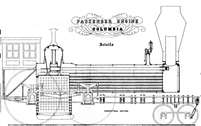
Longitudinal section and
details of the Columbia
The bottom of the firebox water space was the
lowest part of the boiler and thus served as the collecting point for loose
scale and mud. One or more blow-off cocks, usually fitted to the rear of the
firebox, were used to eject all impurities that accumulated at that point.
Washout plugs or hand holes (also for cleaning) were located here.
Before 1860, copper and wrought iron were the
only materials used for firebox construction. At first iron was favored, but
its reedy texture and propensity to blister when under the direct action of
fire caused Stephenson to adopt copper for the firebox's inside sheets in about
1832. Early United States builders followed the British example, and copper
remained the favored material for this purpose until the 1860's. Because of
copper's low tensile strength and increased weakness when heated, it was
necessary to make firebox sheets very heavy. Rear tube sheets (the front sheet
of the firebox) were generally from two-thirds to three-quarters of an inch
thick if made of copper. The crown side and rear sheets were thinner, probably
from five sixteenths to three-eighths of an inch thick. A copper firebox (1,850
pounds) weighed nearly twice as much as an equivalent iron firebox (1,000
pounds) and cost nearly eight times as much ($540 versus $70).38 The higher cost was
justified in part by the longer life of a copper firebox when compared to that
of the iron. This was undoubtedly true when wood was the fuel, but soft copper
sheets were rapidly worn out by fly ash from coal. The Reading complained that
copper fireboxes wore out after only fourteen months service when fired with
anthracite coal.39
The Baltimore and Ohio found that the bituminous fly ash did not cut away
copper sheets so quickly and that about three and a half years' service could
be obtained.40
The Pennsylvania Railroad also found soft coal to be easy on copper plates and
used copper fireboxes for six years.41 This must be considered a record, although it
was not so-reported. Most roads found copper expensive and short-lived for coal
burning.
Thick copper sheets not only increased costs but
reduced efficiency. While copper might be supposed a better heat conductor than
iron, in practice, iron plates were found equally efficient in transmitting
heat because of their thinness. In effect, thick copper plates insulated the
water. This defect, added to the others already outlined, led to the general
abandonment of copper fireboxes in the United States during the 1860's. In 1870
the Baldwin Locomotive Works produced 280 locomotives. Only 6 of these had
copper fireboxes; the rest had fireboxes of steel.
Iron fireboxes were used as early as 1836 by the
Beaver Meadow Railroad for coal-burning locomotives. The Reading found this
material best suited for coal-burning engines when it began to convert to
anthracite in the late 1840's. Iron fireboxes should not be associated
exclusively with coal-burning, however. The Baltimore and Ohio preferred copper
fireboxes for their soft-coal engines, while many builders produced
wood-burners with iron fireboxes, largely because iron was cheaper than copper.
Thus, copper or iron was used for either fuel although copper was preferred for
wood engines before 1860. In 1860 Colburn stated that "the firebox is
always of iron" in American locomotives. This was another indication of
iron's triumph over copper.42
English plate was preferred by most American
locomotive builders. Millholland, however, was not satisfied with commercially
produced firebox iron, imported or domestic, and took a direct hand in its manufacture. He
procured the largest charcoal wrought-iron blooms available and worked them
over with a steam hammer in the Reading shops. After determining that the iron
was of the best quality, the blooms were sent out to a rolling mill for
manufacture. Exceptionally large plates, from 10 to 12 feet long and 6 feet 10
inches wide, were thus obtained.43
Iron had no sooner succeeded copper as the
favored firebox metal when it was challenged by steel. In 1860 Millholland was
reported to be using steel fireboxes.44 The Taunton Locomotive Company built a steel
firebox for the Erie Railway in the same year, which gave good service for ten
to thirteen years.45
Other builders began to offer steel fireboxes but these were not entirely
satisfactory. As with the earliest steel boilers, the plate used was too hard
and cracking was common. Softer alloys soon became available and by the
mid-1860's steel fireboxes were common. The Pennsylvania Railroad had 400
locomotives with steel fireboxes in 1869; some of these had been in service,
for six or more years.46 The success of the steel firebox is further
shown by the Baldwin records for 1870, which note that the vast majority of new
engines were so-built.
Not all master mechanics found steel
satisfactory for fire-boxes. Samuel Hayes respected steel's good qualities but
found iron more durable on the Illinois Central, where bad water: was the rule.47 Wilson Eddy was much
sharper in his dissent and claimed that steel firebox sheets became brittle
like "glass." He did not believe that steel was a miracle metal and
stated: that he would welcome more criticism of the "new-fangled"
material. Eddy's viewpoint was undoubtedly shared by other. old-time master
mechanics and was in line with his conservative approach (viz., his attacks on
Consolidation and Mogul locomotives) to the entire idea of locomotive reform.
Eddy's opinion carried little weight and most roads went ahead with the
conversion to steel fireboxes during the 1870's.
The rapid rise of steel for fireboxes must be
credited to its long life in such wearing service. With good water a steel
firebox would last 300,000 miles or about fifteen years.48 An iron firebox gave
only about three years' service. Thus, under the best conditions a steel
firebox would last nearly the entire life expectancy of the boiler.49
35 Holley, American and European Railway Practice, p. 91.
36 Master Mechanics Report, 1885, p. 48.
37 Modern Locomotives, p. 7.
38 Holley, American and European Railway Practice, p. 20.
39 Whistler, Anthracite Coal, p. 18.
40 Ibid.
41 Holley, American and European Railway Practice, p. 15.
42 Clark and Colburn, Recent Practice, pp. 55, 58.
43 Engineer, February 8, 1861, p. 6.
44 American Railway Review, August 9, 1860.
45 Master Mechanics Report, 1875, p. 23.
46 Institution of Civil Engineers, Proceedings, Vol. 28 (1869), p. 45'
47 Master Mechanics Report, 1872, p. 28.
48 Master Mechanics Report, 1876, p. 76.
49 Ibid. A boiler was well past its prime after twelve years of use. After twenty years wrought iron boilers became brittle "like very poor cast iron." This is very likely true, but many wrought-iron boilers are known to have given up to thirty years' service.
COAL-BURNING
FIREBOXES
pp. 105 - 108
Although a few roads operated coal-burning
locomotives as early as the 1830's, this fuel was not widely used until many
years later. Coal was scarce and expensive, while wood was plentiful and cheap
until this time. Moreover, when serious experiments with coal-burning began in
the late 1840's, the idea was soon established by ill-advised inventors that
only specialized fireboxes could burn coal successfully. The designs offered
were highly contrived affairs where novelty and complexity rather than
performance appeared to be the goal. Any design, as long as it did not resemble
the ordinary firebox, was offered as a solution to the "coal-burning
problem." Dimpfel, Boardman, and Phleger patented their plans and saw
several locomotives built, but with no practical results. Rogers, Baldwin, and
Norris produced their own, somewhat less complex designs but, again, offered
little of value. By the late 1850's most responsible builders agreed that the
standard firebox with minor modifications was well suited for coalburning. It
was further agreed that the problem was not so much firebox design as good coal
and skillful firing. This is not to say that some notable changes were not
made, but rather that firebox design was modified rather than revolutionized
for coal burning.
This view was well stated in the American
Railway Review of July 12, 1860: "We are at last adopting the belief that
the proper combustion of coal can be effected without any structural
modifications of the ordinary boiler, and, beyond a few air holes, a hodfull of
fire-bricks, or a different form of grate, we are insisting upon the retention
of the locomotive boiler as it is, and upon its proper behavior under the
discipline of coal-burning."
The most fundamental modification for
coal-burning engines was the increase in firebox size. Ross Winans was
unquestionably a pioneer in this field and was the first to build locomotives
with large grate areas for coal-burning. In 1847 he built several eight-wheel
coal-burners for the Reading, each with a grate area of 17.6 square feet. A
common wood-burner in this period had a grate area of only about 10 or 12
square feet. During the next few years Winans devised a firebox of increased
size so that by 1850 or 1852 his engines offered grate areas of 24.5 square
feet. Winans' firebox and boiler designs are traced in the drawings shown in
Fig. 37. In 1844 he abandoned the vertical boiler and adopted the Bury boiler.
This boiler did not provide adequate space for the firebox and was modified in
1847 to include a boxlike structure at the back of the boiler, which increased
the grate area. In 1848-49 the arrangement was improved by moving the large,
Bury style dome forward and making a "step" over the firebox. This
helped to balance the boiler by reducing weight at the firebox end but it did
not provide a much-enlarged grate. In 1850 or 1852 the familiar slope-backed
firebox was adopted. This firebox was not a Winans design as is commonly
believed. It can be traced back to Isaac Dripps's 1848 plan for several
Crampton type engines built for the Camden and Amboy Railroad (1849-53).50 Dripps may have borrowed
the idea from an earlier design.
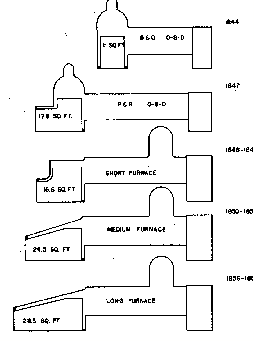
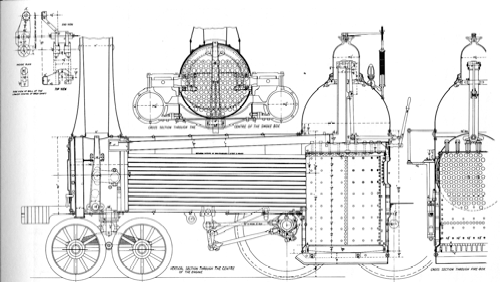
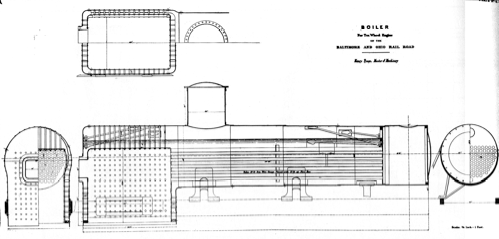
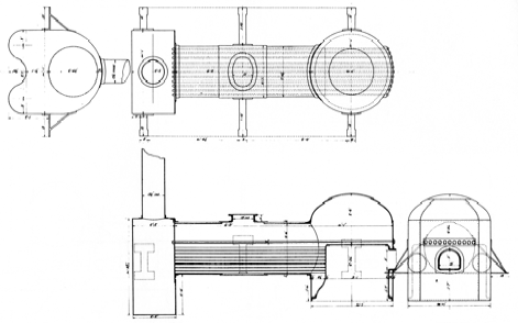
Fig. 37 Horizontal
coal-burning boilers developed by Ross Winans from 1844 to 1857.
James Millholland was another designer who
recognized the importance of large fireboxes for coal-burning.51 Benefiting from Winans' experience,
Millholland began to perfect a coal-burning firebox for the Philadelphia and
Reading Railroad. His early work involved the rebuilding of several engines
with . enlarged fireboxes (1849-51). Unfortunately, Millholland was sidetracked
from any fruitful results for the next four years by adhering to an impractical
scheme for central combustion chambers which he patented in 1852. The central
combustion chamber was abandoned in about 1855 and a slope-backed design was
adopted. Millholland used the slope-backed firebox at early as 1852 but
unfortunately combined it with the central combustion chamber. He used two
small steam domes, thus making a stronger boiler than Winans' large, Bury style
dome. In about 1858 Millholland introduced the water grate as a means of
increasing grate life. This form of construction required a water space at the
rear of the firebox. Previously,. Millholland had copied Winans' questionable
practice of using no rear water space.
Both the Winans and the Millholland firebox had
fallen from favor by 1870 (for reasons unknown to the author) and neither had a
lasting effect on boiler design. They did demonstrate, however, that a simple,
straightforward firebox of sufficient size was practical for coal-burning.
Winans and Millholland increased the firebox
size by lengthening it. Both inventors achieved modest grate enlargements by
making the firebox as wide as the boiler frame (42 inches) but this represented
a rather small increase in size. Dripps built an engine, the Monster, in
1836-38 with a firebox 43 inches wide. Wilson Eddy increased the width of the
firebox slightly by introducing slab rail frames in 1851. Colburn's giant
Lehigh, built in 1856 for the Delaware, Lackawanna and Western, had a firebox
90 inches in width, but this design lay dormant until 1877 when it was revived
by J. E. Wootten. Essentially, firebox enlargement was confined to longer
rather than wider units until the 1890's when the above frame designs became
more common.52
Other than increased size, the firebrick arch
and the combustion chamber were the most important and long-lived alterations
in firebox design made before 1860. Both devices were intended to improve
combustion and the efficiency of coal-burning boilers. The combustion chamber
was an extension of the firebox into the boiler's waist. The purpose was to
provide more room for combustible gases and air to mix for burning. It was
thought that this could be accomplished more readily in an open chamber than
within the boiler tubes. This was a good arrangement for large, modern boilers
but on the whole it was self-defeating in the small boilers used before 1890. A
combustion chamber of any great length shortened the tubes and thus materially
reduced the heating surface. Aside from this consideration the chamber was a
common source of leaks, a defect not easily corrected until the advent of
modern welding in the twentieth century.
The combustion chamber was in evidence as early
as 1832 on the Camden and Amboy Railroad.53 Dripps also used a combustion chamber on the
Monster (1838) and on several Crampton locomotives (1849), all on the Camden
and Amboy line. Despite this long-established use, the idea was patented in
England by Stubbs and Gryll in 1846. As coal-burning engines became more
common, interest in combustion chambers became widespread. Millholland, Winans,
and other advocates of coal-burning adopted this scheme at an early date. A. F.
Smith, while master mechanic of the Hudson River Railroad, carried the idea to
its extreme by equipping eleven passenger locomotives with combustion chambers
5-feet long. It was claimed that this alteration saved some $60,000 per year in
fuel.54 Few combustion chambers
in this period were more than 18 inches long and many were only 6 inches deep.
The fire arch, like the combustion chamber, was
designed to enhance combustion by improving the mixture of unburned fuel gases
and air in the firebox. This was accomplished by increasing "flame
length," but the fire arch did not take space away from any other element of
the boiler as did the combustion chamber. Water legs and cast-iron fire arches
were used experimentally before 1850, but all such contrivances had a common
failing in that they burned out under the direct action of the fire.
This problem was solved by the firebrick arch,
which was not readily consumed by fire. George S. Griggs is commonly credited
with this invention but Matthew Baird is said to have used the device as early
as 1854 on a number of engines built by the Baldwin Works.55 Baird did not patent
the firebrick arch and thus, if the Baldwin history is correct on this point,
lost credit for one of the most notable single contributions to locomotive
design. Griggs first used the brick arch in 1856 and secured a patent on December
15, 1857 (No. 18883). The patent specification reveals that Griggs apparently
was not aware of the chief merit of the fire arch, the fact that the flame is
lengthened by its passage around the arch; at least there is no mention of this
in the patent. The inventor claims instead that the arch is heated by the fire
to the point of igniting the air and gases as they pass over it. This matter
aside, the firebrick arch was rapidly accepted as part of standard boiler
construction. It could be added to existing boilers; in fact, Griggs developed
it to convert wood engines to coal. Not all authorities agreed that it effected
any measurable fuel economies, but it was recognized by all as an effective
smoke preventer. 56
50 A drawing of Dripps's 1847 slope-backed boiler is included in the 1884 Master Mechanics Report.
51 James Mill Holland and Early Railroad Engineering," U.S. National Museum Bulletin, No. 252 (1967), Paper 69. :
52 Millholland is credited with building the above-the-frame firebox engine, the Vera Cruz, in 1857.
53 Sinclair, Development of the Locomotive Engine, p. 384.
54 Colburn and Holley, The Permanent Way, p. 160.
55 History of the Baldwin Locomotive Works, p. s7.
56 Master Mechanics Report, 1877, p. 104.
GRATES
Grates were a simple, trouble-free mechanism in
the days of wood-burning. Cast-iron bars, often T- or V-shaped, answered
construction needs very well. Each bar was about five-eighths of an inch thick,
four inches deep, and as long as the firebox required. The bars were set about
one inch apart. Because the wood was all but entirely consumed in burning,
rocking grates were not required. The small amount of ash that was not thrown
out through the stack filtered through the grate bars to the ash pan.
Coal presented many more problems and required a
more elaborate grate. It produced a hotter fire, and cast-iron bars burned out
quickly. In 1849 it was reported that ordinary iron grates burned out in one
month.57 Some years earlier
Eastwick and Harrison had designed a wrought-iron grate specifically for
coal-burning. In this plan a U-shaped slot in the top of each bar was filled
with clay.58
The effectiveness of this arrangement is not known, but apparently it was not
successful, because no other reports exist on its subsequent use. A more
successful and longlived arrangement was Millholland's water grate. The grate
was formed of iron tubes that connected the front and rear water spaces of the
firebox. The water grate is illustrated in Fig. 39. Millholland first used the
water grate in about 1858 and saw it used by many other roads burning
anthracite.
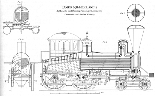
Fig. 39. Millholland's
coal-burning passenger locomotive the Hiawatha, built in 1859 at the Reading
shops. Note the large firebox, water-grate bars, metal cab, and smokebox
superheater.
Most coal-burning roads found rocking grates cheaper and less
complex than Millholland's water grate. The rocking grate was in fact
considered indispensable to soft-coal burning. Bituminous coal formed massive
clinkers which in turn cut off the air supply. The rocking grate assisted in
breaking up these clinkers and reactivating the fire. The exact date of the
introduction of this apparatus is unknown, but Ross Winans offered a simple
plan for the rocking grate as early as 1847. Winans' arrangement consisted of
individual, loose bars that could be tipped from side to side with a jacking
bar. This style of grate was used by Winans on his Camel locomotives until the
end of their production in the late 1850's; it is shown in the Susquehanna
drawing, Fig. 169. More complex rocking grates, connected so that all the bars
might be actuated by a simple lever were introduced in the mid-1850's.
57 Whistler, Anthracite Coal, p. 18.
58 Harrison, The Locomotive, p. 69.
GRATE AREA AND HEATING
SURFACE
p. 110
The importance of adequate grate area and
heating surface was recognized early in the history of locomotive design.
Although there was a tendency to "over-cylinder" engines, heating
surface and cylinder cubic area were held at a remarkably constant ratio (about
200 to 1) between 1835 and approximately 1880. There was, however, an
intelligent movement to enlarge the heating surface proportionately more than
cylinders as the locomotive grew in size.
The typical 4-2-0 of the 1830's rarely had a
heating surface of more than 400 square feet, which was quite adequate for slow
speeds and small cylinders. In the next decade the advent of the heavier 4-4-0
made 500 square feet of heating surface common, with cylinder diameters ranging
from 13 to 15 inches. In the late 1840's and early 1850's the development of an
enlarged heating surface moved forward rapidly. Clobber observed in 1851:
"The heating surface of locomotive boilers has of late years been
considerably increased, not only having been extended with the enlargement of
the cylinders but in a much higher ratio."59 Thus, we find engines
of the early 1850's with 15-inch cylinders but a heating surface of more than
700 square feet. The enlargement of heating surface showed much slower progress
during the next few decades. Yet several designers produced machines with
exceptional heating surfaces. In 1851 Wilson Eddy built the Addison Gilmore with the un-precedented
heating surface of 1,175 square feet. Winan Camel engines built between 1848 and
1860 had heating surfaces of about 1,000 square feet.
Grate area closely followed the expansion of
heating surface The early British and American locomotives of the 1830's
generally had grate areas of about 6 square feet. By the 1840's grate areas of
10 square feet were common. The abandonment of the Bury boiler in the 1850's
made grates of 12 and even 14 square feet possible. Again, as with heating
surface, little real progress was made until after 1875. Most standard-gauge
4-4-0's rarely had grate areas of more than 16 square feet until the 1880's.
Exceptions are of course to be found, particularly with hard-coal or
broad-gauge engines. Winans' and Millholland's coal-burners had grates of 24
square feet and the Delaware, Lackawanna and Western's Lehigh had a grate a of 45
square feet. But such engines were decidedly peculiar American practice of that
time.
During the 1880's the locomotive experienced a
new growth in size which by the end of the decade had become a revolution. By
the mid-1890's firebox area had increased in size by 75 per cent. In these same
years heating surface increased by 45 per cent. Boiler waists formerly limited
to 50-inch diameter jumped to 60 inches, and a few large freight engines had 72
inch boilers.60
59 Colburn, The Locomotive Engine, p. 57.
60 Modern Locomotives, pp. 7 - 8.
pp. 111-114
The
blast or exhaust pipes were located in the smokebox and directed the waste
steam out the smokestack. The use of exhaust steam to create a strong draft, so
essential to the successful working of a locomotive boiler with its high rate
of combustion, was a British invention. It was introduced by Trevithick on his
first locomotive in 1804, despite the conflicting claims of later engineers for
the honor. The value of the blast pipe was not fully recognized until the
1830's when relatively high-speed locomotives were required for public
railways. It became apparent that for such work a locomotive must steam
rapidly, yet stay within reasonable size and weight limitations. A strong draft
caused by the powerful exhaust of steam through a contracted exhaust opening
produced the desired results without an elaborate or extensive apparatus.
Unfortunately,
the idea was carried to an extreme. Small diameter blast pipes soon became the
fashion. Exhaust nozzles (the top opening of the blast pipe) were generally
held to a 13/4-inch diameter for 15inch cylinders. This restricted opening did
indeed create a powerful (and noisy) exhaust. It was reported that "these
tremendously sharp nozzles made no end of a row, each steam stroke going off
like a rifle, or the roar of a Mississippi steamboat; but nobody in the States
ever used the indicator in those days, and there was no knowing what was going
on inside the cylinder.61 Noise was only a by-product of the
actual defects of the small blast pipe. Power-absorbing back pressure was the
chief problem. Robert Stephenson estimated that at high speed a locomotive
fitted with a small diameter blast pipe lost half of its power.62 Not all American engineers were ignorant
of the back-pressure problem, but since speed was of no consequence and rapid
steaming was, small-diameter blast pipes stayed in favor until the mid-1850's.
Colburn called for much-enlarged blast pipes as early as 1851 and praised
Taunton for building engines with 23A-inch blast-pipe nozzles.63 Nevertheless, most early American
engines, because of their small beating surfaces, could not produce sufficient
steam without a powerful exhaust. With increased beating surface and more consideration
given to scientific design and better-proportioned parts, the diameter of
exhaust nozzles increased noticeably after the late 1850's; most builders began
to adopt openings of 3 or more inches.
The
height of the blast pipe developed inversely, becoming shorter and shorter.
Blast pipes made by early British builders protruded into the base of the
smokestack. American manufacturers copied this practice, as can be seen from
the Robert Fulton, Lancaster,
and Dunham drawings.
Tall blast pipes persisted until the 1850’s when they generally extended no
higher than the top row of tubes. The pipe became lower in the next few years.
"It has lately become quite customary, however, to place the mouths [blast
pipe] even with the lower row, or near the lower row of tubes, and to suspend a
short pipe, say three feet long and 8 or 10 inches in diameter, directly over
the exhaust pipes."64 The device just described was the
petticoat pipe, Ross Winans' invention of about 1848. Its purpose was to create
a more even "pull" or draft on all of the tubes. Without it, the
strongest draft was on the upper tubes, the draft on the bottom being so weak
that the lower rows often filled up with ash and cinders. This uneven pull
reduced the beating surface and the steaming quality of the boiler. The
petticoat pipe became quite popular and was much used after 1855. The drawings
of Rogers' 4-4-0 and Erie's No. 254
illustrate this device. The Southport drawings show a variation on Winans' single petticoat pipe which is
made up of three short telescoping pipes.,
While
the blast pipe was the universal method of creating a draft in locomotive
boilers, it might be mentioned that the Baltimore and Ohio Grasshoppers used a
fan. These fans were powered by a small turbine operated on exhaust steam. In
this system the draft could be varied according to the needs of the engine. It
was, however, a complex arrangement and was not widely used.
The
steam jet was another device used for draft, but it was only an auxiliary to
the regular blast pipe. The steam jet's main function was to keep steam up when
the engine was standing at a station. The steam jet was simply a steam line
running to the base of the smokestack with a valve in the cab to be opened or
closed by the enginemen as required. A. F. Smith, of the Cumberland Valley
Railroad, is credited with its invention in 1852. 65
VARIABLE EXHAUSTS. The contracted blast
pipe was a valuable invention that did much to promote the proper working of
the steam locomotive, but its size was fixed and was therefore only generally
suited to the widely varying workings of the locomotive. At times a stronger
blast might be needed to enliven a sluggish fire. Conversely, it might be
desirable to increase the engine's power by enlarging the exhaust nozzle, thereby
reducing back pressure. A contracted blast pipe naturally created a certain
amount of back pressure which under normal circumstances did not materially
reduce the engine's power. But in emergencies, such as getting a heavy train
over a steep grade, relieving the back pressure by opening the nozzle might
provide the extra degree of power required to ease the train over the hill.
Just as the steam was governed variably by the throttle, some engineers thought
that the exhaust should be subject to the adjustments a working engine
required. It was also believed that a worthwhile fuel economy could be
effected.
The
earliest record of a variable exhaust is a drawing of the locomotive Pioneer
built in 1832 by Rothwell for the Petersburg Railroad.66 The drawing shows a conical plug mounted
on top of the blast pipe. The plug was raised or lowered by a simple lever
arrangement, thus opening or partially closing the exhaust nozzle. Three years
later the Paterson and Hudson River Railroad fitted its engine the McNeill with
a conical-plug variable exhaust.67 This contrivance was not a success, because the cone,
pointing downward, deflected the exhaust steam and thus prevented its free
passage out of the stack. In 1836 the famous French engineer De Pambour
experimented with a shutter-valve variable exhaust on an engine of the
Liverpool and Manchester Railway. His design was not a startling success, but
the description of this experiment in his widely circulated treatise on
locomotives attracted attention to the variable exhaust as a promising
auxiliary for locomotives.68
As
indicated above, the idea of the variable exhaust was familiar to American
builders by 1840 (though it was not widely used); yet Ross Winans was issued a
patent on the device in November of the same year. The patent drawing (No.
1868) shows two arrangements of the conical-plug exhaust, one of these being
identical to the 1832 variable exhaust of the Pioneer. Winans may have been
unaware of the Pioneer or the McNeill arrangement, although he sold engines to
the Paterson and Hudson River Railroad. But whether the invention was his by
accident or by cunning, Winans made full use of the patent in later years.
Probably all of his Camel engines were equipped with it, and the variable
exhaust was one of several patents that charged a $750 fee per engine. The
Philadelphia and Reading and the Baltimore and Ohio Railroads used a variable
exhaust based on Winans' plan, not only on their Camels, but on other engines
as well. The Philadelphia and the Tyson Ten Wheeler (see figure below) are so
equipped. Winans' patent was extended in 1854. During the next few years other
builders began offering coal-burning locomotives, and variable exhausts were at
first considered necessary for coal-burning. Winans, however, was careful to
see that his competitors did not infringe upon his invention. Many patent suits
developed. As in the case of the eight-wheel car patent, Winans devoted his
full energies to the prosecution of any trespassers. In 1861 a United States
circuit court ordered Charles Danforth to pay Winans $3,000 for unauthorized
use of the variable exhaust on two locomotives.69

Variable Exhaust for the Tyson Ten
Wheeler
To
avoid Winans' patent, innumerable variable exhausts were devised. Between 1840
and 1915 the United States Patent Office issued 132 patents for such devices.
In the end the variable exhaust was not widely accepted in this country except
during the early years of coal-burning. Once the great “scare" was over
and it was realized that outlandish boiler designs and complex auxiliaries were
not required for coal-burning, the variable exhaust was virtually abandoned in
the United States. It was another complex device to maintain, rarely was it
properly regulated by the enginemen, it clogged up with cinders, and
deterioration, caused by heat and cinders passing at great speed through the
smokebox, was rapid. Finally, the variable exhaust in its closed position could
materially increase back pressure in the cylinders.
Variable
exhausts had become all but extinct in the United States by 1870, although a
few roads, such as the Reading, used them until about 1900. The British were
disinterested. Only the French employed them enthusiastically.
61
Engineering, July 26, 1867, p. 66.
62
Colburn, The Locomotive Engine, p. 67.
63
Ibid., p. 55.
64
Railroad Advocate, July 7, 1855, p. 3.
65
Clark and Colburn, Recent Practice, p. 71; see also "The Pioneer” U.S. National Museum
Bulletin, No. 240 (1964), Paper 24.
66
A drawing of the Pioneer reproduced from an original appeared in the Railroad
Gazette, April 12, 190 1, p. 251.
67
American Railway Review, April 4,1861, p. 199.
68
Variable exhausts, including a history of Parnbour's and Winans' work, are
discussed in a paper by J. S. Bell in the Master Mechanics Report for 1915.
69
American Railway Review, April 4, 1861, p. 199.
pp. 152 – 155
INTRODUCTION
Writing in 1871, Gustavus Weissenborn clearly
recognized the main characteristic of the American locomotive in the following
statement: "The first and most prominent quality of the American
locomotive is its flexibility; in rounding curves, in moving over a rough and
uneven track, yielding in all directions, it maintains both its position on the
rails and its adhesion to them in a surprising manner." This remarkable
agility was the result of a carefully designed running gear, the chief elements
of which were a leading truck, a light bar frame, and equalizing levers. While
these features distinguished the nineteenth-century locomotive from the
standard European model, it has been pointed out in recent years by British
locomotive historians that each of these features can be traced to an earlier
British origin: the truck to Chapman, 1812; the bar frame to Bury, 1830; and
the equalizer to Hackworth, 1827. These claims are valid and there is no reason
to question them; however, in the author's opinion the major point is that
these devices were perfected and used in this country many years before they
were accepted in British practice. In this light it appears reasonable to hold
that the American locomotive running gear was a distinct departure from early
British designs and a leading contribution by American mechanics to this branch
of the technical arts.
SUSPENSION
The need for flexible locomotives was quickly
met by American mechanics, who devised limber, yet stable, locomotive
suspensions. The rapid acceptance of the leading truck after 1832 temporarily eased
the demand for improved suspension. The4-2-0, with its center bearing truck,
offered a stable three-point suspension that could adapt itself to the roughest
track. However, the need for more powerful, coupled engines called for a new
and more complex plan of suspension.

Fig.
57. Andrew Eastwick's patent of 1837 was devised to improve the suspension of
the new 4-4-0 locomotive. The design was not successful, however, and was
superseded by Harrison's plan (see Fig. 58).
The first plan for improving the suspension of
coupled locomotives was that of Andrew M. Eastwick, a partner in the
Philadelphia firm of Garrett
and Eastwick. Eastwick's idea was obviously prompted by the success of the
leading truck; in his plan the driving axles were carried in a separate truck
attached to the locomotive's main frame. The first engine built with this
arrangement, the Hercules, was completed early in
1837 for the Beaver Meadow Railroad;1 Eastwick's patent drawing is reproduced as Fig.
57. Joseph Harrison, Jr., a partner of Eastwick's, materially improved his
associate's plan by discarding the separate locomotive frame. Instead, Harrison
devised several methods to connect the driving axles by means of ordinary leaf
springs and connecting levers, all of which were attached to the main frame.
The object of this arrangement was to distribute the road shocks received by
any one driving axle to the other axles, thereby reducing the likelihood of
derailments or damage to the running gear. In addition, traction was improved
by keeping all driving wheels in contact with the rails. Ilarrison's patent of
April 24, 1838 (No. 706), shows four methods of suspension (see Fig. 58). The
first scheme was not used. The second was used at first by Eastwick and
Harrison. The Baltimore and Ohio Railroad and Ross Winans favored this simple
plan whereby a long leaf spring served as both spring and equalizer. The idea
can be traced back eleven years prior to Harrison's patent to Timothy
Hackworth, who is known to have used an identical arrangement on the locomotive
the Royal George.2 It is probable that
Harrison was unaware of Hackworth's earlier use of the spring-equalizer, for it
was not adopted in England at the time of its introduction and only came into
use in that country after 1851 when it was reintroduced as a "new
reform."3
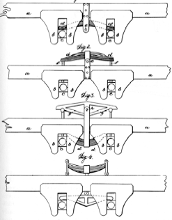
Fig. 58. Harrison's 1838
patent for locomotive equalizers was a basic and widely used improvement.
To return to Harrison's patent of 1838, we find
that the third scheme, a large leaf spring under the frame and attached to a
lever connecting the two driving axles, was used by Eastwick and Harrison on
some of their later engines, notably on the fast passenger engine the Mercury. The Franklin Institute
cited an eight-wheel engine, similar to the Mercury, equipped with
Harrison's equalizing lever in its report for 1839.4 The suspension described
was on the third plan offered in Harrison's patent:
The improvement invented by Messrs. Eastwick
& Harrison is designed to obviate this difficulty, by giving to the
eight-wheel engine only two bearing points, one on the guide truck, and the other
on a frame supported by the driving wheels. The axles of the drivers are placed
one in front, and the other behind the firebox, and are confined between
pedestals of the usual form, fixed to the main frame of the engine, which allow
vertical play, but prevent any horizontal motion.
The bearing pins instead of abutting against
springs fixed to the frame in the ordinary manner, are jointed to the
extremities of horizontal beams of cast iron, one of which is placed on each
side of the engine.
To the centre of these beams or levers, are
jointed wrought iron rods, which pass down through he engine frame, and carry
the springs which support the weight of the engine.
Unfortunately the name of the engine was not
given, but it was credited with pulling a heavy train with ease. It was also
noted that "the road [was] in such bad condition as to keep the sustaining
beam in continual vibration." The final scheme shown in this patent was
apparently not used.
Curiously enough the one arrangement of
equalizers and springs which became most common was not covered by Harrison.
This standard plan called for a leaf spring over each driving axle with a lever
between to coordinate the entire suspension into one complementary mechanism.
To prevent any possibility of bypassing this patent, Harrison greatly enlarged
the original 1838 specification by securing a "reissue" of the old
patent on November 21, 1842. The reissue was, in fact, a new patent in which
several new equalizing schemes were claimed. Among these was the standard
spring-equalizer-spring arrangement, several elaborate bell-crank lever
combinations, and one curious chain and spring arrangement. The 1842 reissue
firmly established Harrison's claim to this highly important invention. He
reportedly received enormous royalties, for few, if any, American locomotives
were built without equalizers after 1840.
It is not surprising that other mechanics
developed new suspension plans in the hope of bypassing Harrison's patent. One
of the first such plans was Henry Waterman's patent of February 10, 1841 (No.
1969). Waterman proposed a separate frame for the driving axles, but unlike
Eastwick's, his plan provided for both lateral and vertical movement by means
of either hinge or ball-and-socket joints. A long radius rod, attached to the
front driving axle pedestal, connected the subframe to the locomotive. This
connection was also hinged.
While there is no record that Waterman's invention was tested, a remarkably similar scheme, which did undergo a number of tests, was patented on February 10, 1843 (No. 2951), by Septimus Norris and William Knight. As in Waterman's patent, a long radius rod connected the subframe to the loco motive; however, Norris and Knight made a second connection with a pivot near the front axle (see Fig. 59). The patentees were forced to recognize the broad claims of the Eastwick and Harrison patents and restricted their claims to the very narrow limits of their peculiar arrangement. For some reason, Norris and Knight were not required to mention Waterman's patent in their patent specification, despite the similarity of the two plans.
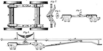
Fig. 59. Norris and
Knight's 1843 patent for locomotive suspensions was an attempt to avoid using
Harrison's invention. Itwas not successful and -was used for only a few years
by Norris.
Several Norris locomotives are known to have
used the Norris and Knight suspension; one of these machines, the Virginia
(Fig. 60), was delivered to the Winchester and Potomac Railroad some months
before the patent was issued.5 Two large lithographs
issued by Norris between 1843 and 1845 show eight-wheel engines so-equipped. A
number of European locomotives are also known to have used this type of
suspension.6 Norris
advertisements appearing in the American Railroad Journal throughout 1845
contain a line cut of a similarly equipped 4-4-0. After the intense promotion
effort, however, Norris abandoned the plan for the simpler and more effective
Harrison equalizer.
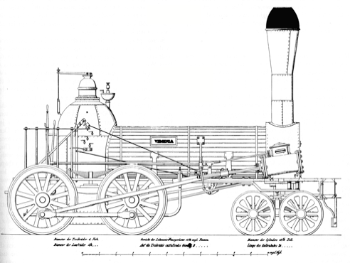
Fig. 60. The Virginia
incorporated the Norris and Knight suspension shown in the preceding
illustration. This engine was built by Norris for the Winchester and Potomac
Railroad in 1842.
1 Railroad Gazette, April 22, 1892, p. 294.
2 Marshall, A History of the Railway Locomotive Engine, p. 173.
3 Colburn, Locomotive Engineering, p. 79. R. & W. Hawthorn, a British firm, obtained a patent for compensation levers in 1851.
4 Harrison, The Locomotive, pp. 67-71, reprinted from the Franklin Institute's 1839 report.
5 Karl von Ghega, Die Baltimore-Ohio eisenbahn . . . (Vienna, 1844), p. 162, reports seeing the new locomotive the Virginia on the Winchester and Potomac in May of 1842.
6 Railway and Locomotive Historical Society, Bulletin, No. 79 (1948), p. 62.
CAST-IRON TIRES.
pp. 181 - 182
The chilled cast-iron tire was the only
competitor of wrought iron until the advent of cheap steel tires in the 1860's.
Cast iron had proved itself an admirable material for car wheels as far back as
the mid-eighteenth century. The life expectancy of such wheels was materially
increased in about 1812 when chilled or "case-hardened" wheels were
introduced in England.84 The tread of the wheel was chilled by making
that portion of the wheel mold of iron rather than sand. Thus the molten iron
was more quickly cooled or chilled when it touched the iron segment of the
mold. The metal was crystallized to a depth of about half an inch and offered a
very hard, durable running surface. The economy and easy manufacture of such
wheels naturally led to an early investigation of chilled cast-iron driving
wheels. Seth Boyden is said to have used an all-cast-iron driving wheel with
hub, tread, flange, and spokes cast in one piece on his first locomotive, the
Orange, completed in 1837.85 A line drawing of the
Orange made by P. 1. Perrin, a former employee of Boyden, shows a wheel of this
construction.86
However, D. M. Harris insists that the Orange was originally fitted with
wrought-iron tires made by his father.87 At this late date it is impossible to determine
whether or not tireless cast-iron driving wheels were used by Boyden on the
Orange.
It is known that Winans produced similar wheels
in the early 1840's. Production of these wheels was soon abandoned, however,
because the lack of separate tires made it necessary to scrap the entire wheel when
the tread or flange wore through the chill.
The earliest known use of separate cast-iron
tires was on the Camden and Amboy Railroad in 1838.88 This was only a
temporary measure resorted to because wrought-iron tires were not available.
However, two years later the Baltimore and Susquehanna Railroad's annual report
noted the regular use of such tires. "Cast iron wheels with chilled treads
were substituted on locomotives for those with wrought-iron tires which wore so
rapidly and required frequent renewals. Chilled driving wheels 4-1/2 feet [in]
diameter have been running on the road for six months, answering perfectly.
Other railroads have followed and adopted this improvement."
The "other railroads" mentioned above
undoubtedly were the Baltimore and Ohio and the Philadelphia, Wilmington and
Baltimore. Both roads began the use of cast-iron tires in the early 1840's.89 By 1847 these three
roads were said to use cast-iron tires "entirely."90 The Philadelphia and
Reading was another large user of cast-iron tires; this preference was
attributable to the road's chief mechanic, James Millholland, who had been
master mechanic of the Baltimore and Susquehanna when cast-iron tires were
introduced. A number of western lines, the Little Miami, Central Ohio, Galena and
Chicago Union, and others are known to have used cast-iron tires, but the
over-all extent of their employment is uncertain.91 Certainly they did not
seriously challenge wrought-iron tires. The use of chilled tires was in fact
largely restricted to the Baltimore and Ohio, the Baltimore and Susquehanna,
the Philadelphia, Wilmington and Baltimore, and the Philadelphia and Reading
Railroads.
Aside from Winans, L. B. Tyng and Company of
Lowell, Massachusetts, and Bush and Lobdell of Wilmington, Delaware, were the
major manufacturers of cast-iron tires. Bush and Lobdell differed from their
competitors by making a hollow tire, thereby decreasing the dead weight and
producing a more even chill.
The first cast-iron tires were made 2 inches
thick, but by 1853 they had been increased to 3 or 3-1/2 inches for safety.92 It was impossible to
mount cast-iron tires by shrinkage, because cast iron is inflexible; therefore,
bolts or rivets were used to fasten them to the wheel center. The tire was
turned to slip snugly on the wheel center—hence the term "slip
tire," a common designation for cast-iron tires. One of the best methods
for fastening cast-iron tires was patented in 1843 by Thatcher Perkins and
William McMahon.93
Several hook-headed bolts passed through the outer edge of the wheel's rim. The
head of the bolt gripped the edge of the tire; a nut at the inner edge of the
wheel rim drew the tire tightly against the rim. Thus, no holes were made in
the tread of the tire. This method also permitted easy replacement of the tire.
Examples of Perkins and McMahon's tire bolt are shown in Figs. 13 and 29 and in
the wheel drawing for Tyson's Ten Wheeler, Fig. 188.
Cheapness was the major advantage of cast-iron
tires. They were said to cost 5~75 per cent less than wrought-iron tires this
claim is essentially substantiated by the following prices: 94
Set of Four Cast iron
tires 60-inches diameter $176.00
Set of Four Wt iron tires 60-inches diameter $372.00
Aside from their cheapness, cast-iron tires were
easily dismountable and were longer-lived than wrought-iron tires. A set of
Bush and Lobdell tires was reported serviceable after 15 years' use; however,
mileage was not noted.95 No specific reports have been found for
cast--iron tire mileage, but chilled cast-iron car wheels averaged about 80,000
miles.96 The chief defect of
such tires was their lack of adhesion; the hard, chilled. surface, so
wonderfully suited to long wear, made a slick, slippery contact with the rail.
The decline of the cast-iron tire was rapid
after the acceptance of steel tires in the 1860's. By the end of that decade on
3,900 locomotives (or less than 10 per cent of all locomotive in service) were
fitted with cast-iron tires.97 A few years late such tires were no longer in
use for road engines but continu to serve on a limited number of switching
locomotives.98
84 Marshall, A History of the Railway Locomotive Engine, p. 126. In error, the invention of chilled wheels has been repeatedly credited to Ross Winans.
85 Railroad Gazette, June 6, 1902, p. 408.
86 Perrin's drawing originally appeared in Locomotive Engineering, October, 1893, p. 433.
87 Locomotive Engineering, December, 1893, p. 551.
88 Memorandum of Isaac Dripps to J. E. Watkins, September 6, 1885, in United States National Museum (Washington, D.C.).
89 American Railroad Journal, August 6, 1853, p. 506.
90 Ross Winans advertisement, Ibid., June 19, 1847, p. 392
91 American Railroad Journal, December 3, 1853, p. 773.
92 Ibid., August 8, 1853, p. 506.
93 J. S. Bell, The Ear1y Motive Power of the Baltimore and Ohio Railroad (New York, 1912), p. 66.
94 The price of cast-iron tires is from an 1860 sush and Lobdell price list in the saldwin Letters, Historical Society of Pennsylvania the price of the wrought-iron tires is from the American Railway Times, September 21, 1861, p. 365.
95 J L. Bishop, A History of American Manufactures (Philadelphia, 1866), p. 545.
96 Figures for car-wheel mileage coflict Galton (Report to the Lords, p. 4) gives 60,000-80,000 miles; Clark and Colburn (Recent Practice, p. 54) report 50,000-100,000 miles.
97 Master Mechanics Report, 1869, p. 42.
98 Weissenborn, American Locomotive Engineering, p. 172.
99 Ahrons, The British Steam Locomotive, p. 162.
Gowan and Marx, 1839
pp. 287 - 289
The Gowan and Marx, one of the earliest 4-4-0's
constructed, was built for slow-speed coal traffic. It won international
acclaim for hauling a train forty times its own weight. Famous in its own time,
it remains today one of the best known early American locomotives.
The Philadelphia and Reading company ordered the
Gowan and Marx in the summer of 1839 from Eastwick and Harrison of
Philadelphia. The machine was named for a London banking firm. A short wheel
base, a concentration of weight on the driving wheels, and a large firebox and
boiler combined to produce a compact and powerful locomotive. The total weight
was 11 tons with 9 tons on the drivers. The wheel base measured 10 feet; the
drivers were set only 3 feet 8 inches apart. The engine developed an estimated
147 horse power at its usual operating speed of 8-10 miles per hour.1
The records differ on the precise cylinder and
driving-wheel size. A report issued by G. A. Nicolls, superintendent of the
Philadelphia and Reading, on February 24, 1840, stated that the cylinders had a
12-2/3-inch bore and 16-inch stroke and that idle drivers were 40 inches in
diameter. Karl Ghega, an Austrian engineer who examined the railroads of the
United States in 1842, agreed with Nicolls on the cylinder dimensions but
stated that the wheels were 42 inches in diameter. Writing in 1872, Joseph
Harrison, the engine's designer, recalled a cylinder size of 12-1/2 inches by
18 inches and wheels 42 inches in diameter.
Joseph Harrison, lr.
(1810-1874), a partner in the firm that built the Gowan and Marx.
A Bury-style boiler was used, but the firebox
was oblong, thus providing a larger fire grate than did the usual round shape.
This variety of Bury boiler was used by Eastwick and Harrison on other
locomotives. The inside of the Gowan and Marx firebox measured about 48 inches
long by 36 inches wide. The boiler shell was approximately 40 inches in
diameter and contained 129 tubes, each 2 inches in diameter. The steam pressure
varied between 80 and 130 pounds per square inch.
The feed-water pump was placed in the cylinder
saddle parallel to the cylinder itself. The saddle, warmed by the steam passing
to and from the cylinder, preheated the feed water and prevented the pump from
freezing in the water. This clever design was not, to the best knowledge of the
writer, used by other United States builders. One objection may have been the
interference or cramping of the steam passages by placing the pump in the
already crowded saddle casting. The pump was driven by the crosshead. The
center of the pump and the crosshead guide were about 10 inches apart. This
great distance undoubtedly caused severe racking of the crosshead and was
unquestionably a constant source of trouble.
The valve gear, patented by Andrew M. Eastwick
on July 21, 1835, was favored by Eastwick and Harrison. The valve ports were
cast as a separate block and were shifted to reverse the engine. Only two fixed
eccentrics were used. The beauty of this design was its simplicity, but it was
effective only in forward motion. Because of the peculiar problems created by
shifting the ports rather than the valve, the valve had no lead. A small lap
was possible on the outside of the valve but not on the inside. This poorly
conceived valve operated well enough in forward motion but permitted only slow
speeds in reverse. The cutoff, as with other early valve gears, was not
variable. The position of the eccentric is an open question. The placement of
the rear driving axle under the firebox and the narrow clearances of the frame
and boiler make it difficult to determine how an eccentric of sufficient size
was attached. The drawing, Fig. 122, shows the eccentric rod (item 9) extending
from inside the frame, but the clearances are not sufficient to permit this
placement. The best compromise, but admittedly not entirely satisfactory, is a
small eccentric under the firebox.
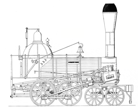
Fig. 122. A side
elevation of the Gowan and Marx.
The Eastwick reversing block was used as late as
1861 on some 4 4-0's built by Harrison, Eastwick, and Winans for the Volga-Don
Railway.2 The addition of a
cutoff valve vas an important modification of Eastwick's earlier arrangement.
The most important mechanical feature of the Gowan
and Marx
is the equalizing lever. The device was basic to the success of the coupled
locomotives and was used from its inception in 1837 until the end of steam
locomotive construction. Andrew Eastwick originated the idea of equalizing in
his patent of November 20, 1837 (No. 471), but was unable to develop a
practical design. His partner, Joseph Harrison, perfected a workable design and
secured a patent on April 24, 1838. The heavy cast-iron beam used on the Gowan
and Marx is representative of the earliest type of equalizer used in the United
States. The Peoples Railway No. 3 exhibited at the Franklin Institute has
equalizing levers of this type and was consulted for the Gowan and Marx reconstruction (Fig. 126).
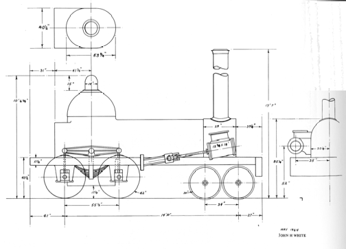
Fig. 126. The Peoples
Railway's No. 3, now exhibited by the Franklin Institute. The exact identity of
this ex-Reading locomotive is unknown, but it was probably built by Eastwick
and Harrison in about 1842. Note the firebox extension on the rear of the
boiler and the cast-iron equalizing lever.
No data is available on the tender used for the Gowan
and Marx except that it weighed 6 tons. It was
undoubtedly a common four-wheel U-tank tender of the period..
The reconstruction drawings of the Gowan and
Marx (not shown herein) were based on the primarily
on Ghega drawing. Another contemporary drawing was prepared in 1841 by Enoch
Lewis, an employee of Eastwick & Harrisson.3 This drawing is
preserved in the John B. Parson Collection at Columbia University. The Lewis
and Ghega drawings agree exactly in general arrangement and boiler details but
differ markedly in the running-gear detail. A riveted frame with massive plate
pedestals is shown. The wheels are T- rather than oval-spoked. A double-hook
valve gear is shown rather than the Eastwick arrangement. The truck has a bar
frame with individual springs for each wheel in place of the "spring"
truck shown in the Ghega drawing. In short, the Lewis drawing differs enough
from the Ghega drawing to indicate a rebuilding of the Gowan and Marx between 1839 and 41. A third
contemporary drawing of the Gowan and Marx in a French publication
of 1843.4 The engraving agrees more closely with the Lewis
drawing and the Ontalaunee . The most notable mechanical variation from
Ghega's drawing is the large spring used in place of the equalizing lever.
Other minor variations will be seen in the me, truck, valve gear, and feed
pumps.
Having briefly described the Gowan and Marx , a few notes will be
added concerning its history. The Gowan and Marx was eighteenth locomotive completed by
Eastwick and Harrison. It was used to pull the first train between Reading and
Philadelphia on December 5, 1839. On February 20, 1840, it pulled a train of
101 four-wheel cars weighing 423 tons from Reading to Philadelphia. This
remarkable performance established a permanent place in railroad history for
the Gowan and Marx.
It so enhanced the reputation of Eastwick and Harrison that they were invited
to Russia to build locomotives for the Moscow and St. Petersburg Railway.
Curiously, despite their reputation, Eastwick and Harrison were not large
builders. Before leaving the United States in 1844, they had built fewer than
50 locomotives.
The Gowan and Marx was originally designed to
burn hard coal, but did not prove a success with this fuel. Wood was used until
January, 1855, when the engine was again converted to burn coal. The conversion
was not entirely successful, for the 1857 Philadelphia and Reading annual
report notes that the Gowan and Marx was again rebuilt in August, 1856.5 Its weight was reported
to be 13.8 tons, which indicated some major alterations. An extension of the
firebox similar to that added to the Peoples Railway No. 3 (Fig. 126) would
explain in part the additional 2.8 tons. This boxlike projection enlarged the
grate area enough to permit successful coal-burning.
After twenty years and over 144,000 miles of
service on the Reading, the Gowan and Marx was traded to the Baldwin Locomotive
Works as partial payment for a new locomotive. The old engine was probably sold
off to work out its last days in some obscure corner of industrial America. Its
final disposition is unknown.
1 Ghega, Die Baltimore-Ohio Eisenbahn.
2 The Engineer, March 12, 1880, p. 199. In this article Ross Winans was incorrectly credited with building locomotives in Russia.
3 The Lewis drawing was reproduced in A Century of Reading Company Motive Power. p. 12.
4 Annales des Points et Chanssee's (2nd series; Paris, 1841-45), Plate 47.
5 Annual report of the Philadelphia and Reading for 1856, table.
MANUSCRIPT SOURCES
Baldwin,
M. W. Papers, Letters, and Account Books. ca. 183666. Historical Society of
Pennsylvania, Philadelphia, Pa.
Baldwin
Locomotive Works. Specifications. De Golyer Foundation Library, Southern
Methodist University, Dallas, Texas.
Hinkley
Locomotive Works. Register. 1841-56. Boston Public Library.
Patten
Papers. Letters of G. W. Whistler and Joseph G. Swift. New York Public Library.
Robert
Stephenson & Co. Specifications. 1828-40. English Electric Co., Ltd., Newton-le-Willows,
England.
Rogers
Locomotive Works. Specifications. 1845-46 (scattered copies). Smithsonian
Institution, Washington, D.C.
BOOKS
Ahrons, E. L. The British Steam Railway
Locomotive, 18251925. London: The Locomotive Publishing Co., 1927. An excellent
historical survey of British locomotive engineering with line and halftone
illustrations.
Alexander, Edwin P. Iron Horses. New York: W. W.
Norton & Co., 1941. A pictorial work valued for the many contemporary
lithographs reproduced. Also included are line drawings reprinted from
Weissenborn's American Locomotive Engineering and Railway Mechanism and
Railroad Gazette.
Bell, J. Snowden. The Early Motive Power of the
Baltimore and Ohio Railroad. New York: Angus Sinclair Co., 1912. One of the few
dependable technical histories on American locomotives. The author was a
draftsman with the Baltimore and Ohio as a young man and had first-hand
knowledge of his subject. Line and halftone illustrations.
Bendel, A. Aufsatze Eisenbahnwesen in Nord-Amerika (text and
atlas). Berlin, 1862. An official government report on U.S. railroad operations
and equipment similar to Galton's 1857 report. Line drawings of Winans' Camel
and Tyson's Ten Wheeler.
Brown, William H. The History of the First
Locomotive in America. Revised ed. New York: D. Appleton & Co., 1874. A
chatty account based largely on recollections. Concerned mainly with the
Stourbridge Lion and locomotive "firsts." Little technical
information. Line cuts.
Bruce, Alfred W. The Steam Locomotive in America.
New York: W. W. Norton & Co., 1952. A comprehensive technical history of
American locomotives after 1900. Bruce was chief engineer of the American
Locomotive Company; his comments on modern practice are knowledgeable and
represent an outstanding contribution to locomotive history. As a historian,
however, Bruce failed badly; his comments on early practice are scanty and too
often incorrect. Regrettably, no documentation was offered. Line drawings and
photographs illustrate this valuable work.
Century of Reading Company Motive Power, A.
Philadelphia: The Reading Companv, 1941. An illustrated summary of locomotive
development on Reading lines. Convenient for quick reference.
Clark, Daniel K. and Colburn, Zerah. Recent
Practice in the Locomotive Engine. London, 1860. Offered as a supplement to
Clark's early work on railway machinery, this volume was devoted almost
entirely to British locomotives. The two American engines illustrated and
Colburn's history of American practice made this work invaluable to any study
of the subject.
Colburn, Zerah. Locomotive Engineering and the
Mechanism of Railways. 2 vols. London and Glasgow, 1872. This work was nearly
complete in 1864 but was not published until after the author's death. Only one
American locomotive, a Rogers 4-4-0, is illustrated by a full set of drawings
in this large work, but the detailed history offsets this omission in large
part. It is an invaluable reference.
—. The Locomotive Engine. Boston, 1851. A
small book intended for the practical mechanic. While largely non-theoretical,
it treats the elements of steam and combustion. Specific locomotives are
described, together with notes on their performance. The work is New England
oriented. It was in print long after its content had become obsolete.
Colburn, Zerah, and Holley, Alexander L. The
Permanent Way and Coal-Burning Locomotives. New York, 1858. Primarily European
in content, it is useful for its illustrations of specialized fireboxes
developed to burn coal.
De Pambour, C. F. M. G. A Practical Treatise on
Locomotive Engines upon Railways. 1st English ed. London, 1836. The first
technical book devoted entirely to locomotives. It established formulas,
proportions, and general theories that were followed for many years in
locomotive construction. A widely read and influential work. Illustrated with
drawings for a Stephenson Planet engine.
Ferguson, Eugene S. (ed.). Early Engineering
Reminiscences (1815-1840) of George Escol Sellers. Washington, D.C.: Government
Printing Office, 1965. Recollections by an early locomotive builder who was
associated with Baldwin, Norris, Brandt, and other pio neers in the field.
Illustrations and annotations added by the editor.
Forney, Matthias N. Catechism of the Locomotive.
1st ed. New York: Railroad Gazette, 1874. Prepared as an instruction book for
engineers and plain mechanics, this volume explains the workings and general
construction of American locomotives. Properties of steam and the theory of the
cutoff are explained. This and other early editions contain a set of assembly
drawings for a Grant 4-4-0. The work remained a standard reference for many
years and went through several editions.
Locomotives and Locomotive Building. Originally
put fished New York: W. S. Gottsberger, 1886. 2nd ea., Berkeley, Calif.: Howell-North
Books, 1963.
A combination illustrated history and catalog of
the Rogers Locomotive and Machine Works. Many line cuts of early components and
general designs for early Rogers locomotives as well as the history of the
works and its founder are included.
Galton, Douglas. Report to the Lords of the
Committee of the Privy Council for Trade and Foreign Plantations, on the
Railways of the United States. 2 vols. London: Eyre and Spottiswoode, 185758.
Text and atlas. A general survey of operations, construction, and equip ment
with line drawings of cars, locomotives, and rails. A small but valuable
report.
Gerstner, F. A. Ritter von. Die innern
communication der vereinigten Stuaten von NordAmerica. Vienna, 1842-43. A
classic two volume study of American railroads by a recognized Austrian
engineer. Much technical information and detailed notes on operations are
offered. Many engravings of early track are given, but only one plate on
locomotives, a detail on spark arrestors, is included. Data gathered 1838 40.
Ghega, Karl von. Die Baltimore-Ohio
Eisenbahn.... Vienna, 1844. Text and atlas of plates. A more general treatise
than the title implies, this work contains comments on Norris, Baldwin, and
Eastwick and Harrison, as well as several fine engravings of locomotives. The
data for the book were gathered from about 1840 or 1841 through 1842.
Hlarrison, Joseph, Jr. The Iron Worker and King
Solomon. Philadelphia, 1869. Contains a fine essay on Harrison's career as a
locomotive builder both in Philadelphia and in St. Petersburg, Russia.
______The Locomotive and Philadelphia's Share in
its Early Improvements. Philadelphia: Gebbie, 1872. The recollections of a
central figure in the development of the American locomotive. Mention is made
of Norris and Baldwin as well as of the more minor Philadelphia builders.
Illustrated with line cuts.
History of the Baldwin Locomotive Works, The.
Philadelphia: Baldwin Locomotive Works, 1923. This is an updated version of the
business history that first appeared in the 1873 Baldwin catalog. It presents a
convenient, if incomplete, history of the firm. Illustrated with tables on
production.
Hodge, Paul R. The Steam Engine.... New York: D.
Appleton & Co., 1840. Text and atlas of plates. The earliest work to
contain complete drawings of an American locomotive. The author was a draftsman
for Dunham and Rogers. Stationary and marine engines are also treated.
Holley, Alexander L. American and European
Railway Practice. New York: Van Nostrand, 1861. An expansion and revision of
Colburn's and Holley's The Permanent Way and Coal-Burning Locomotives. It
treats mainly coal-burning locomotives and track and is largely European in
content.
Jervis, John B. Railway Property. New York,
1861. A general manual treating construction and management of railroads, with
historical references to Jervis' early work with truck locomotives.
Lardner, Dionysius. Railway Economy. New York
and London, 1850. A general work, mainly European in emphasis, but a useful
firsthand account of early American locomotive operations.
Lucas, Walter A. From the Hills to the Hudson.
New York, 1944. Mainly a corporate history of the Paterson and Hudson River
Railroad and associated lines. It contains some detailed data on the early
locomotives of this line.
Marshall, C. F. Dendy. A History of the Railway
Locomotive Engine down to the End of the Year 1831. London, 1953. The best of
several excellent works by this author on early locomotive and railway
engineering. Marshall was an engineer who understood the historian's craft and
gathered together much obscure information on the beginnings of steam
locomotives.
Matthias (1st name unknown). Darstellung, einer
zum Transport-Betrieb auf der Berlin-Potsdamer Eisenbahn im Gebrauch
befindlichen Locomotive . . . Norris in Philadelphia. Berlin, 1841. Folio work
devoted entirely to the description of the Norris 4-2-0. Plates are reproduced
in the present work.
Meyer, J. G. A. Modern Locomotive Construction.
New York, 1904 Based on a series of articles which appeared in the American
Machinist more than ten years earlier, the contents of this work treat
locomotive designs of the 1880's. The text explains the rationale of the
standard designs employed by American builders. Few general assemblies but over
a thousand drawings of component parts are included. The author was chief
draftsman at the Grant Locomotive Works.
Modern Locomotives. New York: Railroad Gazette,
1897. A folio-size collection of drawings with a good introductory summary on
locomotive developments since 1890. Reprinted in 1901.
Mone, Fredrick. An Outline of Mechanical
Engineering. New York(?), 1851. A complete set of working drawings and a fine
mechanical description of the locomotive Croton are included in this work.
. A Treatise on American Engineering. New York,
1854. Devoted mainly to stationary and marine engines but containing drawings
for two Hudson River Railroad locomotives, the Columbia and the Superior. Text
is general and of minor importance compared to the drawings.
Norris, Septimus. Norris' Handbook for
Locomotive Engineers and Machinists. Philadelphia, 1853. Tables and very
general comments copied from earlier British works.
Pangborn, J. G. The World's Railway. New York,
1894 and 1896. A rambling, inaccurate history of locomotive development
compiled by the manager of the Baltimore and Ohio exhibit at the Columbian
Exposition. The author was a journalist and had little understanding of
engineering. The work is valuable, however, for its record of the recollections
of S. B. Dougherty, an early associate of W. T. James. The curious u ash
drawings illustrating the text are of questionable value.
Recent Locomotives. New York, 1883. A collection
of engravings and articles which appeared in the Railroad Gazette between 1871
and the time of publication. Some mechanical drawings included. Expanded and
reprinted in 1886. Modern reprint of the first edition, by Graham Hardy (1950).
Reuter, Emil. American Locomotives.
Philadelphia, 1849. Text and atlas of plates. The first attempt to describe
American locomotives, in which only about a third of the projected forty-two
plates were printed. The text also appears to be incomplete. The drawings are
of great value and include complete plans for the Philadelphia, an 0~0, the
Delaware, an 0-8{), and the John Stevens, a 6-2-0. The author was a draftsman
employed by both Millholland and Winans.
Ringwalt, James L. Development of the
Transportation Systems of the United States. Philadelphia, 1888. A useful
digest of transport history to that date. Little is offered on locomotive
construction, but some good material on railroad operations is included.
Sinclair, Angus. Development of the Locomotive
Engine. New York, 1907. An ambitious attempt to chronicle the American
locomotive which has been a standard reference on the subject since its
publication. Its value is greatly impaired by numerous errors, a lack of
documentation, and too great a reliance on recollections. Should be cautiously
consulted
Stevens, Frank W. The Beginnings of the New York
Central Railroad. New York, 1926. Primarily a corporate history of the early
roads that later combined to form the New York Central. The author has
assembled much good data on the early locomotives of the Mohawk and Hudson
Railroad.
Stevenson, David. Sketch of the Civil Engineering
of North America. London, 1838. general travel account that includes a chapter
on American railroads. Notable for its description of the cowcatcher.
Tanner, Henry S. A Description of the Canals and
Railroads of the United States. New York, 1840. Little material on railroad
equipment but several detailed descriptions of operations and track
construction.
Vose, George L. Handbook of Railroad
Construction. Boston, 1857. Brief description of locomotives including a few
outline drawings. Valuable for its references on fuels.
Warren, J. G. H. A Century of Locomotive
Building by Robert Stephenson ~ Co., 1823-1923. Newcastle, England, 1923. An
excellent history of the world's first commercial locomotive builder, with
outstanding technical descriptions of design and development illustrated by
original drawings. Many early locomotives exported to the United States are
described. In the present author's opinion, it is the finest locomotive history
printed in the English language.
Wleissenborn, Gustavus. American Engineering.
New York, 1861 (text) and 1857 (atlas). A collection of handsome line
engravings described by a very general text. The engravings of the Talisman are
the only locomotive drawings in this work.
._____American Locomotive Engineering and
Railway Mechanism. New York, 1871. A large folio work with magnificent line
drawings for eleven American locomotives, most of which date from the late
1860's. Baldwin, Cooke, Hinkley, and the products of several railroad shops are
represented. One of the best works ever published on American locomotives. The
plates were reprinted by the Glenwood Publishers (1967).
White, John H., Jr. Cincinnati Locomotive
Builders, 18451868, Washington, D.C.: Government Printing Office, 1965. A
business history of the largest center of early Midwest builders. Some notes on
design and construction.
Wood, Nicholas. A Practical Treatise on
Rail-Roads. Ist ed. London, 1825. One of the earliest works to discuss
locomotive construction. The 1832 edition has an appendix on American railways.
Yoder, Jacob H., and Wharen, George B.
Locomotive Valves and Valve Gears. New York, 1917. Excellent technical work.
Except for link motion, only modern valve gears are treated.
REPORTS
American Railway Master Mechanics Association
Annual Report. 1868 to the present. Detailed reports on mechanical problems and
developments. Some line drawings after about 1875.
American v. English Locomotives, Correspondence,
Criticism and Commentary Respecting their Relative Merits. New York, 1880.
Baltimore and Ohio Annual Report. 1827-75.
Cohen, Mendes. Report on Coke and Coal Used with
Passenger Trains, on the Baltimore and Ohio Railroad. Baltimore, Md., 1854.
Eastern Railroad Association—Annual Reports
of Executive Committee. Boston, Springfield, and New York, 1867-83. The main
function of this association was to report on patent claims made against member
railroads.
Knight, J., and Latrobe, B. H. Report upon the
Locomotive Engines . . . Several of the Principal Rail Roads in the Northern
and Middle States. Baltimore, Md., 1838.
New England Association of Railway
Superintendents—Report of the Trial of Locomotive Engines. Lowell, Mass.,
1852.
Palmer, William J. Report of Experiments with
Coal Burning Locomotives Made on the Pennsylvania Railroad. Philadelphia, 1860.
Philadelphia and Reading Annual Report. 1839-70.
Lists locomotives, v.ith notes on rebuilding.
Report of the Canal Commissioners of
Pennsylvania. Harrisburg, Pa., 1825-ca. 1857.
Reports for 1835 to 1840, valuable for
locomotive data on the Philadelphia and Columbia and Allegheny Portage
railroads.
Report of the Railroad Commissioners of New
York. Albany, N.Y., 1856 only.
Operating statistics and list of locomotives for
all New York railroads.
South Carolina Canal and Railroad Company.
Report of the Committee on Cars.... Charleston, S.C., 1833.
Mainly concerned with locomotives, with special
reference to Allen's articulated locomotives.
Strickland, William. Reports on Canals, Railways,
Road, and Other Subjects Made to Pennsylvania Society for the Promotion of
Internal Improvements. Philadelphia, 1826.
American report on British transport.
Whistler, George W., Jr. Report upon the Use of
Anthracite Coal in Locomotive Engines on the Reading Rail Road. Baltimore, Md.,
1849.
PERIODICALS
The various railroad and technical journals
listed below were by far the most valuable sources of information found for specific
technical details. The journals were far more pertinent to engineering history
and development than were any of the books available on the subject.
American Railroad Journal. New York, 1832-86.
Little on engineering after about 1860.
American Railway Review. New York, 1859-61.
American Railway Times. Boston, 1849-72.
Engineer (London). 1855 to the present.
Engineer (Philadelphia). 1860 only. Zerah
Colburn was the editor. The journal was similar to the Railroad Advocate.
Engineering. London, 1866 to the present.
Journal of the Franklin Institute. Philadelphia,
1826 to the present.
Locomotive Engineering. New York, 1888-1928.
Angus Sinclair was the editor. See Development of the Locomotive Engine.
Railroad Advocate. New York, 1854-56. The only
early American railroad journal devoted to technical matters.
Railroad Gazette. New York, 1870-1908.
Railway Age. Chicago and New York, 1876 to the
present.
Railway and Locomotive Historical Society Bulletin.
Boston, 1922 to the present. A rich source and a rare hobby journal that is not
devoted to club news.
Railway Master Mechanic Magazine. 1886-1916.
Scientific American. New York, 1845 to the
present.
Return to the Steam Engine Development Page
About The Hopkin Thomas Project
Rev. March 2010