The Metallurgy of
Iron
by
Thomas Turner
Being One of a Series of Treatises on
Metallurgy, Written by Associates of the Royal School of Mines
Charles Griffin & Co., Limited,
Exeter Street, Strand
1908
CHAPTER VII.
Excerpts – pp. 129
- 144
THE AIR USED IN THE BLAST FURNACE.
Blast
Engines.-In India and
other parts of the world where the natives produce wrought iron direct from the
ore, various simple forms of bellows are made from the skin of an animal and
worked by hand; furnaces and bellows of similar design were employed by the
ancient Egyptians many centuries before the Christian era. These were
afterwards replaced by leather bellows with valves, which were at first worked
by hand and afterwards with water power.1 One of the first applications of the steam engine was for
the blowing of air for blast furnaces, and some blowing engines of the early
type are still working in the older iron districts. These engines are of the
Watt pattern, and consist of a massive beam of cast iron supported at the
centre, a steam cylinder being connected to one end of the beam and a blowing
cylinder to the other; low-pressure steam is used, and the engine is worked
with condensers and with a single steam cylinder. Such engines often work for
many years with but trifling repairs, but on account of the great weight of
metal to be moved they can only be driven at a slow rate, they are not so
economical in fuel as more modem engines, and if a fracture of the beam does
occur it usually occasions much damage and loss of time. A drawing of a blast
engine of this kind is given in Fig. 33, while another illustration of a
similar form, together with the necessary pamps, flywheel, &c., is given in
Dr. Percy's Iron and Steel (p.
387).
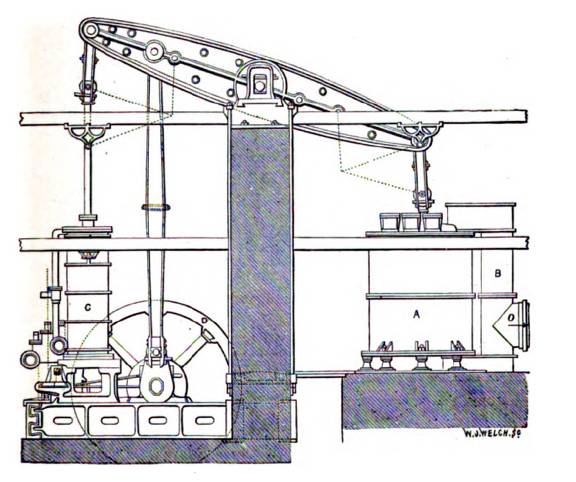
Fig. 33 -Beam Blast
Engine. A, Blast cylinder. B, Blast pipe leading to main, 0.C, Steam cylinder.
D. Fly wheel.
Vertical
direct-acting engines are now generally preferred for producing the blast,
where steam is employed, and the compound principle has been successfully
applied at a number of modem works. As an example of this the blast engines at
the Dowlais Works at Cardiff may be taken. These engines, which are illustrated
in Fig. 34, are worked with a boiler pressure of 100 pounds to the square inch,
and have two steam cylinders, side by side, one 36 inches in diameter for
high-pressure steam, and another, which is steam-jacketed and 64 inches in
diameter, for low-pressure. Connected with, and directly underneath, each steam
cylinder is a blast cylinder 88 inches in diameter. The engines are designed to
ive a maximum pressure of 10 pounds to the square inch, and wworking with a
5-foot stroke at 23 revolutions per minute they give 19,000 cubic feet of air
per minute at atmospheric pressure. There is a separate engine for each
furnace, on the American principle, and the number of revolutions of the engine
is automatically recorded by means of a mechanical counter. The engine is
capable, if necessary, of blowing 25,000 cubic feet of air per minute, and the
pressure actually developed by the engine in ordinary working is rather over 6
lbs. to the square inch.2
A number of American blowing engines
have been illustrated and described in Iron Age, vol. xlvii, pp. 319, 968; vol. x1viii,
pp. 303, 441.
From
information collected by A. von Ihering in 1892 there were in Austria and
Germany 191 blowing engines for blast furnaces; of these 87 were vertical, 70
were horizontal, and 25 were beam engines, while 9 were worked by water power.
It will be thus seen that for blast furnaces vertical engines were generally
preferred, though with higher pressures and smaller volumes of air, as in
Bessemer steel works, horizontal engines are best.3
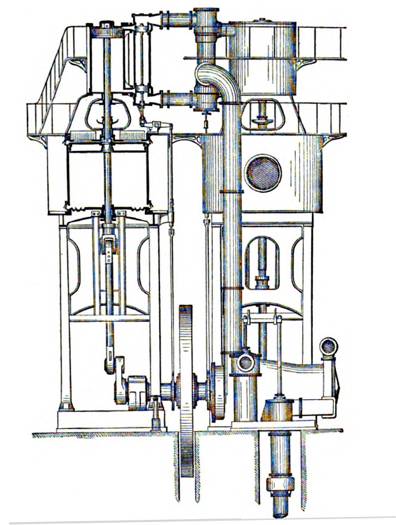
Fig. 34. -Vertical
direct-acting blast engine (Half Section).
Among
the more recent forms of blowing engines two varieties call for special
mention. Steam turbine engines have been introduced in Cleveland and elsewhere,
and are stated to work very economically and to give a very uniform and steady
air pressure. Large gas blowing engines have also been adopted,
Generally
with marked success. The first blowing engine worked by blast mace gas was
erected at Seraing in 1899. It was of 600 horse-power; was worked with
unpurified gas; and has been fully described by A. Greiner.4 Such engines are now driven by means of
the cleaned surplus gases of the blast furnace, and they will be referred to
later when dealing with the utilization of the waste gases of the furnace in
Chapter VIII. Three important papers dealing with the history and design of
large gas engines for blast-furnace gases will be found in the Journal of
the Iron and Steel Institute,
1906, vol. ii. These papers deal with engines in Belgium, in Germany, and in
the United Kingdom respectively.
Application
of Hot Blast.-The
original patent, No. 5,701, granted to J. B. Neilson, of Glasgow, on l1th
September, 1828, for "improved application of air to produce heat in
fires, forges, and furnaces where bellows or other blowing apparatus are
required," reads an follows;
" A blast or current of air must be
produced by bellows or other blowing apparatus in the ordinary way, to which
mode of producing the blast or current of air this patent is not intended to
extend. The blast or current of air so produced is to be passed from the
bellows or blowing apparatus into an air vessel or receptacle, made
sufficiently strong to endure the blast and through and from that vessel, by
means of a tube, pipe, or aperture, into the fire, forge, or furnace. The air
vessel or receptacle must be airtight or nearly so, except the apertures for the
admission and emission of the air; and at the commencement and during the
continuance of the blasting it must be kept heated artificially to a
considerable temperature. It is better that the temperature be kept to a red
heat or nearly so, but so high a temperature is not absolutely necessary to
produce a beneficial effect. The air vessel or receptacle may be conveniently
made of iron, but as the effect does not depend on the nature of the material,
other metals or convenient materials may be used; the size of the air vessel
must depend upon the blast, and on the heat necessary to be produced. For an
ordinary smith's fire or forge, an air vessel or receptacle capable of
containing 1,200 cubic inches will be of proper dimensions; and for a cupola of
the usual size for cast iron founders, an air vessel capable of containing
10,000 cubic inches will be of a proper size. For fires, forges, or furnaces,
upon a greater scale, such as blast furnaces for smelting iron, and large cast
iron founder's cupolas, air vessels of proportionately increased dimensions and
numbers are to be employed. The form or shape of the vessel or receptacle is
immaterial to the effect, and may be adapted to the local circumstances or
situation. The air vessel may generally be conveniently heated by a fire
distinct from the fire to be effected by the blast or current of air, and
generally it will be better that the air vessel and the fire by which it is
heated should be enclosed in brickwork or masonry, through which the pipes or
tubes connected with the air vessel should paw. The manner of applying the heat
to the air vessel is, however, immaterial to the effect if it be kept at a
proper temperature."
From
the above specification, to which no drawings were attached, it will be
observed that Neilson claimed no special form of apparatus, but merely the
principle of employing heated air for combustion. How far he at the time
correctly understood the facts underlying his invention is doubtful, but it is
interesting to notice that even in his original specification Neilson mentioned
the use of a red heat, and throughout his whole life he consistently advocated
the use of the highest attainable blast temperature; the temperature obtained
with the apparatus at first introduced was, however, far below redness.
Theory
of the Hot Blast.-It may
at first sight appear strange that any economy should result from the use of
hot blast, and in the early days of this discovery it was urged that a given
weight of fuel burned in the furnace would give as good a result as if part
were burned inside the furnace and part employed to heat the blast. The
following are some of the more important reasons for the economy observed with
hot blast:
1. In the lower part of the blast furnace
carbon is not oxidized to carbon dioxide (CO2), but only carbon monoxide (CO)
is produced. The combustion of carbon by air forced into the blast furnace,
therefore, generates only 2,473 centigrade heat units, while when complete
combustion takes place, as in heating the blast, carbon generates 8,080 heat
units. The heat liberated by a unit of carbon burned in heating the b1aat is
thus more than three times as great as that yielded by a unit of carbon burned
in the blast furnace.
2. The use of hot instead of cold blast
naturally increases the temperature of combustion near the twyers, and this
assists in the rapid melting of the slag and iron.
3. When the temperature is sufficiently
high, carbon is at once converted into carbon monoxide, and the heat of
combustion is thus localised. In a furnace using cold blast, carbon dioxide is
produced near the twyers, this is decomposed into monoxide somewhat higher in
the furnace, with the result that the reaction is completed further away from
the twyers than with hot blast.
4. Owing to the more local combustion,
and smaller quantity of air employed with hot blast, the upper part of the
furnace is cooler, and the escaping gases carry off much less sensible heat.
5. Owing to the diminished consumption of
fuel, due to the above causes, less ash has to be converted into slag, loss
flux is n6eded, and thus fuel is saved.
6. As less fuel is required with hot
blast, less time is needed for its combustion. A furnace of given capacity
contains more ore, and the yield of the furnace is largely increased.
Although
the heat generated is greater when carbon is burned to CO2 than when CO is
obtained, the temperature is locally higher in the latter case. This is owing
to the fact that CO2 begins to dissociate into CO and O at about 1,200 C to
1,300 C., and hence CO can only be completely burned to CO when the temperature
of combustion does not much exceed 1300 C. It is for this reason that the hot
blast, by leading to the immediate formation of CO, yields a higher temperature
in the hearth than would be possible if CO2 were there produced.
The
sensible heat brought into a blast furnace by the blast is generally about
one-seventh of that required by the furnace, though the proportion will vary
with the temperature and volume of blast. A useful table has been prepared by
C. Cochrane,5 giving the equivalent in cwts. of coke,
of the heat brought in by the blast; in this table the weight of blast ranges
from 55 cwts. to 145 cwts. per ton of iron produced, and the temperature from
10 to 800 C., and it thus includes all variations met with in practice.
Limit
to the Advantages of Hot Blast.-It
is obvious that there is a theoretical limit to the temperature which can with
advantage be imparted to the air used in the blast furnace, for since a
reducing agent is necessary to remove the oxygen of the ore, it is not possible
to smelt iron with hot air alone, or with less than the quantity of carbon
needed to remove the oxygen. If, therefore, the minimum quantity of carbon
required for combination were ever reached, it would be useless to further
increase the temperature of the blast. It must be remembered that there are
difficulties in the way of heating air much above the temperature now
attainable, and these difficulties are very great - if not insurmountable.
Owing to the dissociation of carbon dioxide at temperatures little above the
melting point of steel, the combustion of carbon is incomplete, and its full
calorific power cannot be obtained. At the game time the lose by radiation, and
the wear of the heating apparatus, increase rapidly at high temperatures, so
that it becomes more and more costly to raise the air through each succeeding
increment of temperature. This question has been dealt with at considerable
length by Sir L. Bell6 who shows that the saving of fuel on raising
the blast from 1,000 F. to 1,700
F. was only 1 cwt. per ton of iron made, and concludes that it is not
economical to raise the temperature beyond 1,700 F. Sir L. Bell's conclusions
would, however, need some revision in view of modem practice with good
fire-brick stoves, as it does not appear that in actual working the economical
limit has been yet often exceeded or even reached.
Methods
of Heating the Blast.-The
apparatus employed by Neilson in his first practical application of the hot
blast early in 1829 at the Clyde Iron Works, Glasgow, is shown in the following
figure.
Neilson’s original hot
blast apparatus, 1829
.It
consisted of a small wrought-iron heating chamber, 4 feet long, 3 feet high, and
2 feet wide, which was set in brickwork with a grate below like a steam boiler.
The cold blast entered immediately over the grate and passed out at the
opposite end, being warmed in its passage to about 200 F. The blast entered the
furnace by means of 3 twyers, each of which was provided with a similar heating
box. This apparatus was only capable of warming the air, but the results
obtained were such as to indicate the great advantages to be derived from the
application of hot blast. The wrought-iron chamber thus employed not only had
the disadvantage of exposing little heating surface to the blast, but it was
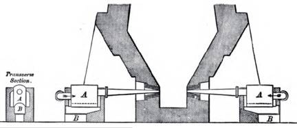
soon burned out and required renewal. It was, therefore, replaced by a
cylindrical cast-iron tube (A), set horizontally in a heating chamber (B) (see
Fig. 35), and, as before, each twyer was provided with a separate heater. These
horizontal pipes gave a higher temperature, but such an arrangement led to
irregular heating, and to much trouble with the expansion and the contraction
of the pipes. Full details of Neilson's early forms of apparatus are given by
H. Marten,7 from whose paper the accompanying
sketches are reproduced.
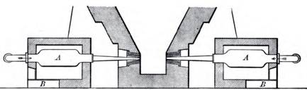
Fig. 35.-Neilson's
cylindrical oven.
The
first cast-iron tubular oven was erected at the Clyde Works in 1832, and is shown
in Fig. 36.
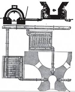
Fig. 36. - Original
tubular oven.
From
this it will be seen that the blast furnace was supplied with 3 twyers, to each
of which was attached a stove, which consisted of a chamber of brickwork,
heated by means of a fire grate placed underneath, and through which the air
passed in a series of circular cast-iron pipes, which were arched over the
fireplace as shown in the sketch. Hot-blast stoves on this principle were soon
adopted in all the chief iron-making districts, numerous modifications of
detail being introduced from time to time. In order to diminish the
difficulties due to expansion of the metal a U or V shape was employed for the
pipes, while to give greater heating surface they were cast with an elliptical
section. The stoves were built larger so as to do away with the necessity of a
separate heating arrangement for each twyer, while in order to obtain a higher
temperature each stove was divided into several separate chambers, and the air
caused to pass through these in succession (Fig. 37).
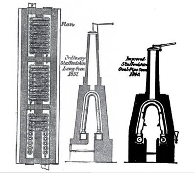
Fig. 37
To
economise space in some cases circular ovens were constructed on similar
principles; the first circular hot blast stove was erected by M. Baldwin in
1851 at Bilston in Staffordshire, and though the heat so obtained was not
greater than in the rectangular form, the trouble due to leakage and fractures
was much diminished (Fig. 38).
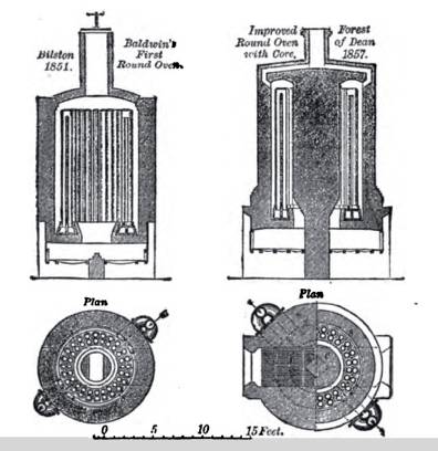
Fig. 38 Round and long ovens
A form of stove which also met with
considerable favour was introduced by Mr. Baird at Gartshorrie, and known, from
the peculiar shape of the heating pipes, as the "pistol pipe" stove:
this is shown in Fig. 39, from which it will be seen that the pipes are divided
by a partition which passes throughout the greater part of their length, and
the air, instead of passing across the stove is made to travel up on the
outside and down the inside of the same divided tube.
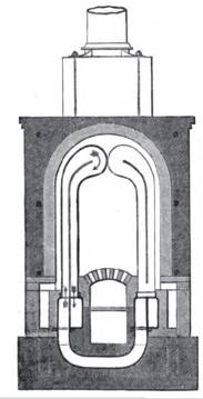
Fig. 39. -Pistol pipe
stove.
Gas-Fired
Regenerative Stoves.-The
early forms of hot blast stove were all heated by the combustion of solid fuel,
and although in 1833 Faber du Faur invented a hot-blast stove heated by the
combustion of the waste gases from the blast furnace, and experiments in the
same direction were conducted at Wednesbury in the following year, it was not
until after Budd’s patent of 1845 that this system of heating was successfully
introduced. Direct-firing stoves held their own side by side with gas-fired
stoves, for a number of years, until the regenerative system invented by
Siemens was applied to heating the blast, with the waste gases, by E. A. Cowper
in 1860. A history of the development of fire-brick stoves has been given by
Luhrman.8
The
Cowper Stove, which is shown in sectional elevation in Fig. 40, consists of an
outer shell of plates of wrought iron or mild steel, riveted to form a
cylindrical chamber some 60 feet high, 28 feet in diameter, and with a
dome-shaped roof. This chamber is lined internally with firebrick, a circular
flue extends from the bottom to the top, while the rest of the chamber is
filled with fire-bricks. The waste gases from the blast furnace enter the
Cowper stove by the gas valve shown in the sketch; the air required for
combustion enters at the air valve, and combustion takes place at A at the base
of the internal gas flue. The hot products of combustion pass downwards through
the regenerator of honeycomb brickwork to the exit valve, which is connected
with the chimney. The mass of brickwork in the regenerator absorbs heat from
the hot gases, and itself becomes red hot, particularly in the upper portion.
When this has gone on sufficiently long to thoroughly heat the brickwork, the
air, gas, and chimney valves are closed, and cold blast is admitted through the
cold-blast main in the opposite direction, when it takes up heat from the
brickwork, an is delivered to the furnace through the ho tblast valve. It in
necessary to have at least two stoves for each blast furnace, so that one may
absorb beat while the other is heating the blast, and it is advisable to also
have a stove in reserve in case of accident. Where blast of higher temperature
than usual in required, as with rapid production, four firebrick stoves are
usually provided for each furnace.
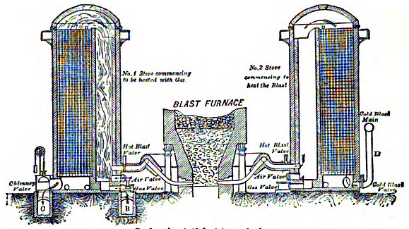
Fig. 40. -Cowper's
hot-blast stoves. Scale, about 60 feet to an inch.
In
the original Cowper stove the bricks were arranged without any binding
material, loosely, as in the Siemens regenerator. Afterwards, about 1875, the
bricks were arranged in rows, with every other brick projecting so as to form
vertical channels. The honeycomb brick employed for the regenerator of the
modern Cowper stove is illustrated in Fig. 41, and is designed, when the bricks
are placed together, so as to form hexagonal gas passages, all of which have
walls of Stourbridge or other refractory fire-clay, 2 inches in thickness. Each
brick is 6 inches in height, and weighs about 32 lbs. In plan these bricks
consist of a hexagonal air passage, the greater diameter of which is 7 inches,
surrounded by a wall of fireclay 2 inches thick; at each of the six comers of
this hexagonal wall, a short projecting wall 2 inches square and 6 inches high
is attached in the direction of the longer diameter, the whole forming one
brick. The projections are so arranged that, on placing the bricks into
position side by side in the stove the whole of the interior is divided into
upright hexagonal air passages, with a larger diameter of 7 inches, and with
fireclay walls 2 inches thick. The bricks are made by pressing the clay into a
column of the required shape by suitable machinery, and cutting off horizontal
slices from this column each 6 inches high; these are dried and baked in kilns
before use. The bricks were formerly reamed separately by hand, but this method
has been replaced y that just described.
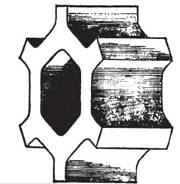
Fig. 41. -Honeycomb brick.
The
combustion flue inside the Cowper stove is usually circular in cross section,
but it is found that with this form the pass have a tendency to pass chiefly
down the centre of the brickwork filling, this being the shorter path, and to
leave the corners comparatively cool. In order to equalise the distribution of
the gases, a D-shaped combustion flue has been introduced as described by W. J.
Hudson (S. S. Inst,
Nov. 1891, Discussion), with the result that the crescent-shaped corners in the
filling of brickwork have been done away with, and a more uniform heating
obtained. At Friedenshfitte, in Upper Silesia, the same object is obtained by a
modification due to Bucker, who, instead of giving a uniform cross-section to
the brickwork passages of the stoves, makes those in the centre, where the
gases travel a shorter path, smaller than those at the sides through which the
travel is longer; this is illustrated in Inst, Journ., 1890, vol. ii., p. 516, and some such
method of equalisation is now frequently adopted.
The
hot-blast valve of a Cowper stove is shown in Fig. 42. The valve seat is of
cast-iron; a wrought iron tube being cast in, and water circulated through the
tube to protect the casting from over-heating. The valve itself is of steel,
and has a sheet of asbestos on each side, which is kept in place by a plate;
this prevents the valve from burning at the high temperatures employed. The
usual temperature obtained by Cowper stoves as employed for blast furnace
purposes is 1,500 F. (815 C.), but a temperature of 2,000 F. can be attained if
desired.9
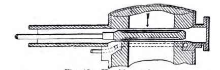
Fig. 42 Hot Blast
Valve
As
compared with pipe stoves the Cowper stove gives a much higher temperature, and
has thus led to an increased yield of about 20 per cent. from similar furnaces;
the fuel consumption is at the same time lessened; in some experiments
conducted by Mr. Hawdon the quantity of gas required by a Cowper stove was only
two-thirds of that of a pipe stove, while the temperature obtained was
1,500 as against 1,000 F. These
advantages have been so fully proved that hundreds of Cowper stoves are now in
use throughout the world, and a number of modifications of the regenerative
fire-brick stove have also been introduced. The Cowper stove probably gives the
highest temperature of any of these varieties, but it has the disadvantage of
being somewhat easily clogged with dust, especially when smelting
finely-divided or manganiferous ores. To minimize this difficulty dust catchers
are often employed (see p. 119). As furnace gases will in future be more
perfectly freed from dust than was formerly the case, the dust nuisance is not
likely to cause as much inconvenience as heretofore. But even under the most
favourable conditions dust accumulates in the Cowper stove, and necessitates.
occasional cleaning. For this purpose C. Wood, of Middlesbrough, employed a
small bronze cannon, which was charged with powder and run into the stove to be
cleaned when the blast was turned off. The charge was fired from outside by
means of a sliding hammer which struck a percussion cap, and which was set in
motion by blowing down a long india-rubber tube. The explosion thus caused
displaced the dust, which was allowed to settle and was afterwards removed.
Another method of cleaning such stoves, which is now in pretty general use,
depends on the use of release valves, such an Lister's, which allow of the
instantaneous discharge of the imprisoned air; in order to remove the dust the
fall blast pressure is turned into the stove, and then by the release valve
this is allowed to pass instantaneously into the chimney. A cloud of dust is
immediately discharged, and being shot up into the air is often visible for
considerable distances. Cowper stoves are now not infrequently raised on
columns so as to allow men to stand underneath for cleaning with a scraper.
This is done at casting time and after the stove has been ou blast for some
time, as the bottom is then comparatively cool.
The
Whitwell Stove.-The
first Whitwell stove was erected at the Thorrnaby Iron Works at
Stockton-on-Tees in 1865. This store is also a regenerative gas-fired stove~
and like the Cowper is constructed of plates of iron riveted together to form a
cylinder, which in modern stoves is some 65 feet high and 25 feet in diameter,
with a dome-shhaped top, and lined throughout with fire-brick. But the internal
arrangement of the two stoves is quite different. Figs. 43 and 44 show a
vertical and horizontal section of a Whitwell stove, in the interior of which
is a regenerator which consists of a series of vertical firebrick passages made
of 5-inch brickwork. The gas is admitted at A at the bottom of the combustion
chamber, while air is introduced by feed passages (a), and the products of
combustion pass to the chimney through the flue (C). The hot and partly burned
gases pass repeatedly up and down through the brickwork passages, and after
giving up their heat to the stove, ultimately leave at a low temperature. Air
is admitted by valves into the feed passages so as to complete the combustion
as the gases pass through the stove, and in this the Whitwell principle differs
from that adopted by Cowper. When the brickwork is thoroughly hot, the gas is
turned off, the cold blast enters the stove at D, takes up heat from the heated
brickwork, and passes out at B on its way to the furnace. The Whitwell stove
not only offers less opportunity for the accumulation of dust, but also, on
account of the shape, allows of more ready cleaning while at work, and is thus
in favour where the gases are more than usually dusty. The stove shown in Figs.
43 and 44 is of the original pattern introduced by Mr. Whitwell; it was 25 feet
high and had a flat roof. The more recent forms are about 70 feet in height,
while an arched top, like that of the Cowper stove, is also adopted.
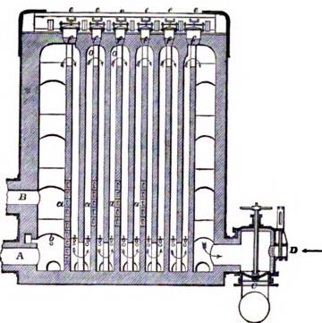
Fig. 43.
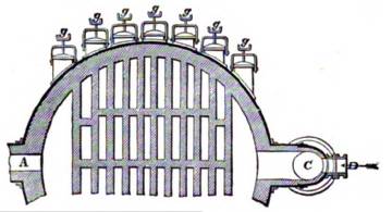
Fig. 44.-Whitwell stove.
Original form.
A
number of modifications has been introduced in the construction of fire-brick
stoves in America~ one common plan being to make them quite independent of the
draught of the stack by providing a separate chimney, with a valve at the top
of each store, but this method has not been adhered to in some of the later
installations. The arrangement of the regenerator has also been modified in
many ways. In the Gordon-Cowper- Whittwell pattern, which is very popular in the Southern States, and
which is shown in sectional elevation in Fig. 45, both the Whitwell and the
Cowper systems are combined, while a separate chimney is provided as is usual
in America. It is claimed that such stoves have the advantage that gases which
contain a considerable proportion of dust may be employed, while as the latter
part of the regenerative action is conducted by Cowper bricks, the gases are
efficiently cooled, and a high temperature can be imparted to the blast.10
In
the Massick & Crookes Stove
the regenerator is on the Whitwell principle, but arranged in what, is known as
a three pass" system; the
main combustion tube is placed in the centre of the stove, and the gases after
passing up the central tube pass ones down and onceup through gas pass-ages
similar in principle to those of the Whitwell stove, but arranged
concentrically around the main combustion tube. The products of combustion pan
out at the top of the stove by a separate chimney11.
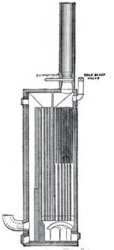
Fig.
45.-Gordon-Cowper-Whitwell stove
The
Ford & Moncur Stove was
introduced in Cumberland some years ago, and has since met with considerable
favour12
.This stove is on the
fire-brick regenerative principle, with the usual external casing of iron
plates lined with fire-brick. The modifications introduced are intended chiefly
to facilitate cleaning: for this purpose bricks are employed, the upper edges
of which are dormer-shaped so as to prevent the dust lodging; the stove is also
divided into four separate parts by vertical partitions, so that, when it is
desired to clear out the dust, the blast is turned on to each section
separately, and by proper release valves the air is allowed to suddenly escape
and so carry away the dust, and it is claimed that the stove can thus be
readily kept clean without any necessity for stoppages. Instantaneous release
valves, invented by Lister, have also been pretty largely adopted for cleaning
other varieties of hot-blast stoves, and materially reduce the deposit which
accumulates during the heating by gas. Hot-blast valves were formerly a source
of much trouble, owing to the burning of the seat and consequent leakage.
Westray and Copeland have overcome this difficulty by the use of cast-iron
valves which have a pipe coiled round the seat; by circulating water through
this pipe the seat is cooled and lasts much longer; at the same time
arrangements are made for bolting on the seat, so that it can be readily
changed when necessary.
1. The
"Development of Blast-Furnace Blowing Engines," from the earliest to
the more modern forms, has been dealt with by D. E. Roberts (Inst. M. E.
Cardiff Meeting, 1906).
2. Inst. Journ, 1899, vol. i, p. 19.
3. Inst. C. E.., vol. exii., p. 432
4. Inst. Journ., 1900. vol. i p. 109.
5. Inst. M. E., 1883, p. 124.
6. Principles, sects. 6 and 7. See
also Inst. Journ.,
1893, vol. ii., p. 242.
7. Inst. M. E, 1859, p. 62
8. Inst. Journ., 1890, yol. ii., p.
754.
9. E. A. Cowper, J. S. C. 1., 1893, p. 311; also S.
Staff. Inst.,
Sept., 1884.
10. Inst Journ. (Amer. vol.), p. 335.
11. Inst. Journ., 1890, vol. ii., p.
340; also ibid.,
Plate 24.
12. Ibid, 1890, vol. i, p. 391.
Return to The Anthracite Iron Industry page
About The Hopkin Thomas Project
Rev. February 2010