Manhattan Gateway
UNDER THE RIVERS
Ed. This excerpt (p. 23 – 35) from Middleton’s
excellent work on the development of rail access by the Pennsylvania R. R. to
Manhattan features the construction process which employed cast iron tunnel
rings manufactured by The Davies and Thomas Company of Catasauqua, Pa. J. McV
By
January 1902 planning for the Pennsylvania's great project had already begun,
and the board of engineers was organized and began its work that month. By the
end of the year the City of New York had approved the franchise, and the work
could begin.
Construction
was divided into four divisions, each under the supervision of a chief engineer
appointed from the board. William H. Brown headed the Meadows Division, which
included an interchange yard at the junction with the main line east of Newark
and the line across the Hackensack Meadows to the west side of Bergen Hill.
(Brown was later succeeded by Alexander C. Shand.) Tunneling expert Charles M.
Jacobs was in charge of the North River Division, which included the tunnels
through Bergen Hill and under the Hudson. Electrical engineer George Gibbs was
responsible for New York station construction and the electrification work.
Alfred Noble headed the East River Division, which included the four East River
tunnels and the huge passenger train service and storage yard at Surmyside.
The
distance, the river depth, and the materials through which the tunnels would be
drilled combined to make the Hudson and East river tubes a project of
unprecedented scope and difficulty. But the work was far from the leap into the
unknown that Dewitt Haskin had taken 30 years before: Much had been learned in
the intervening years, and the technology of underwater tunneling was now much
advanced.
Even
though Haskin did not use it, the idea of the tunneling shield had been around
since Marc Isambard Brunel devised one for his Thames River tunnel constructed
between 1825 and 1843. The shield was a cylindrical structure pushed forward by
jacks. as a tunnel was excavated through soft material, supporting the material
until a permanent tunnel lining was put in place.
James
Greathead designed an improved wrought iron shield for the Tower Tunnel
completed under the Thames in 1869; that tunnel was also the first to have a
cast-iron lining. At about the same time, Alfred Ely Beach, an inventor and the
editor of the Scientific American,
used a cylindrical shield propelled by 18 hydraulic rams to drive the first U.
S. shield tunnel for an experimental subway under Broadway in New York.
Shield
tunneling technology reached maturity near the end of the century with the
completion of the Grand Trunk Railway's St. Clair River tunnel between Sarnia,
Ontario, and Port Huron, Michigan. The project combined compressed air support
of the ground during construction, a movable shield, and cast-iron lining.
Joseph
Hobson,
chief engineer for the tunnel, designed a 60ton shield that was moved forward
by 24 hydraulic rains. Tunnel workers on platforms behind the cutting edge of
the shield excavated the river-bottom clay. A rotating arm on the rear of the
shield lifted sections of the cast iron shell into place, where they were
bolted together. Headings were advanced from both sides of the river, and the
6000-foot tunnel was driven in just a year. The Pennsylvania Railroad would use
the same basic tunneling technology.
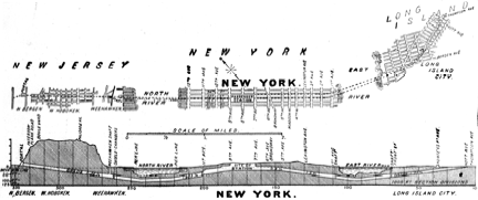
This drawing from the
May 14,1910, issue of Scientific American Supplement shows the alignment and
profile of the Pennsylvania's New York tunnels, from the Hackensack portal in
New Jersey to Long Island City. Science and Engineering Library, University
of Virginia.
The
most challenging portion of the work was the construction of twin tunnels
extending 2.76 miles from the Hackensack portal on the west side of Bergen Hill
to a point under the corner of 32nd Street and Ninth Avenue in Manhattan.
It
was necessary to drill the tubes under the Hudson at a sufficient depth below
the dredging plane established by the War Department (40 feet below mean low
water) to protect them against damage from heavy anchors or sunken vessels, and
to ensure that they could pass below existing piers and bulkheads. The tubes
would also have to be far enough below the bottom of the river to provide
sufficient cover to prevent a blowout during compressed air tunneling.
The
tunnels descended on a 1.3-percent grade from the Bergen Hill portal to a low
point at which the bottom of the tubes was 97 feet below mean high water,
providing an average cover depth of 25 feet between the top of the tunnel and
the river bottom. From this low point, the tunnels climbed for a distance of
5000 feet on grades of 0.53 and then 1.93 percent to level off 35 feet below
street level between Ninth and Tenth avenues.
Surveys,
soundings, and borings confirmed that the tubes would lie in a fluid silt
composed principally of clay, sand, and water. The board of engineers selected
shield-driven, compressed-air tunneling as the most suitable for the work. The
method had the advantage of avoiding any work from the surface that might
obstruct navigation in the Hudson.
The
two single-track tunnels were drilled on 3-foot centers. Each had a circular
cast-iron shell with an outside diameter of 23 feet. Where unusual stresses
were expected, such as a transition from soft to hard ground, cast steel was
used instead of cast iron. Each tunnel "ring" was bolted together
from eleven segments plus a closing "key" segment, each 2 feet 6
inches long and 1-1/2 inches thick. This shell was lined with reinforced concrete
with a normal thickness of 2 feet from the outside of the shell. Concrete
"benches" on either side of the trackway, suggested by Cassatt, were
intended to confine a train to the center of the tunnel in the event of a
derailment. They also served as walkways and provided space for signals.
An
early problem was that of assuring adequate stability of the tubes in the soft
silt of the riverbed under heavy loads. In 1901 Charles Jacobs proposed and in
1902 patented a "subterranean tunnel bridge" design for the crossing
consisting of piers carried to a solid foundation in the riverbed, a truss
bridge carried on the piers, and a tunnel shell surrounding the bridge and
attached to the piers. The bridge structure would carry the live load of trains
directly to the piers, avoiding any deflection of the tunnel. The v truss
bridge scheme was soon discarded in favor of one that called for the use of
shorter girders that would support the track and the trains. They would be
carried on piers spaced at 15-foot intervals.
The
method was tested near the New Jersey bank of the river. The engineers selected
cast-iron screw piles soft ground and then the silt layers under the river,
vary~ ing from 25 to 40 pounds per square inch. Cable-hauled dump cars
operating on 2-foot gauge tracks removed excavated material to the shafts,
where it was lifted to the surface, while flat cars were used to bring in the
cast-iron tunnel segments.
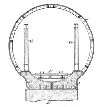
These Patent Office
drawings, reproduced from the February 11 1902, issue of Scientific American,
show the "tunnel bridge" scheme devised by Charles M. Jacobs to
support a tunnel driven through silt or other loose material. The track was to
be carried by steel trusses, which were to be surrounded by the tunnel shell
and supported by piers sunk through the river bottom silt -to rock or other
firm material. Science and Engineering Library, University of Virginia.
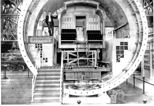
This full-size section
of the Hudson River tunnels was displayed by the Pennsylvania at the 1904
Louisiana Purchase Exposition at St. Louis. Clearly visible are the concrete
benches on either side of the track proposed by A. J. Cassatt. At the bottom of
the tube can be seen the planned track support system carried on screw piles
driven to a solid foundation every 15 feet. These were never installed, and the
openings left for them in the cast-iron tunnel were later closed. Smithsonian
Institution (Neg. 94-4983).
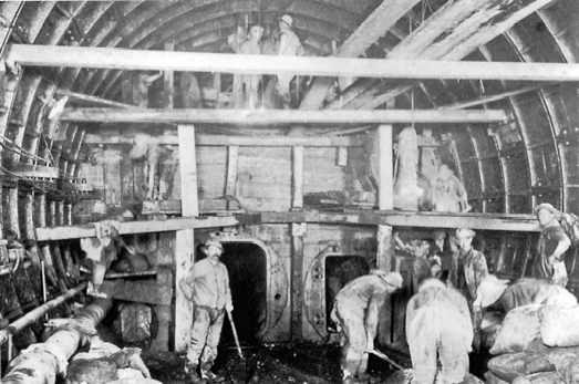
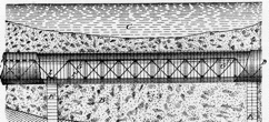
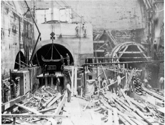
A photograph taken in
the North tunnel on May 17, 1906, shows the 10-foot-thick concrete bulkhead
wall and air locks that separated the pressurized section of tunnel under
construction from the section at lower pressure. Two of these were built about
1200 feet apart in each tunnel heading. This one was installed in the north
tunnel, almost directly below the Manhattan shoreline of the Hudson. Smithsonian
Institution (Neg. 94-4977).
Some
problems were encountered as the tubes pushed out under the Hudson from the
Manhattan side. Where the tubes passed under the bulkhead wall at the edge of
the river, the tunnelers had to bore through pilings and stone riprap
supporting the heavy stone bulkhead wall. As the shield cut into the loose
riprap the compressed air blew out into the ground behind the bulkhead and into
the river. A clay "puddle" - mud made from the excavated silt - was
used to plug the holes in the riprap. Each stone had to be removed individually
by a tunnel worker with a pry bar, while another waited to plug the hole with
puddle.
Each
time the shield was advanced there was a slight "blow" of compressed
air, dropping the pressure within the tunnel. Twice the blow was much greater,
dropping the tunnel pressure enough to allow water to enter the tunnel.
Escaping air created a geyser at least 20 feet high in the river, and water
rose to about 4 feet in the tunnelbefore it could be stopped. For the worst of
these, some 5000 barrels of cement and sand had to be forced through the tunnel
lining behind the shield to bind the riprap together and reduce the loss of
air.
After
making their way through the riprap the tunnelers encountered the wood piling supporting
the bulkhead along the river, and a hundred wood pilings had to be cut out of
the path of each shield. Even after the bulkhead was passed, the loss of
compressed air continued, since there was only a few feet of light silt over
the tunnel. This was finally stopped by dumping 28,000 cement bags filled with
mud into the hole.
As
the tubes advanced into the Hudson River silt, Jacobs expected that the shield
doors could be closed and the shield forced through the soft material without
taking any excavated material into the tunnel, as had been his experience with
the smaller Hudson & Manhattan tunnel he had completed a short time before
between Hoboken and Morton Street in Manhattan. It was discovered, however,
that the shield tended to rise under these conditions, and it proved impossible
to keep the tunnel on the correct grade. Jacobs solved the problem by directing
that some of the shield doors be opened to take in about a third of the
displaced material; this corrected the tendency of the shield to rise as it
progressed. For a time the tunnels even went downward, according to an account
by chief assistant engineer James Forgie, "until it was found they could
be steered vertically by admitting more, or less, silt into the tunnel."
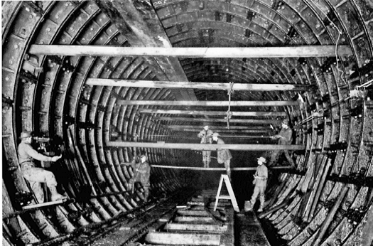
Shown here is some of
the surveying work that helped the tunnelers to work with such precision that
the tubes were within 1/16 inch of perfect alignment when they met under the
Hudson. In this photograph taken on January 17, 1907, the surveyors are
checking line and level through a 6-inch pipe driven between the north tunnel
from the Manhattan side and the south tunnel driven from the Weehawken side
prior to the meeting of the north tunnel shields at mid-river. Hagley Museum
and Library.
It
was also found desirable to increase the weight of the tube to make the weight
of the completed tunnel closer to that of the displaced material. This was done
by increasing the thickness of the cast-iron tunnel lining segments to two
inches. About 2800 linear feet of each tube under the main river channel was
laid with this "heavy iron," adding over 3500 tons to the weight of
each tunnel.
The
tunneling progressed rapidly as the tunnelers gained experience. While it took
as long as 6 hours to erect a single cast-iron tunnel ring in early stages of
the work, this was later reduced to as little as 30 minutes for each ring. The
much more cumbersome "heavy iron" rings were installed in an average
of about I hour 44 minutes. With crews of 24 men at each shield working on
three 8-hour shifts, the average rate of progress in each heading was about 18
feet per day.
The
two shields for the north tube met under the river on September 10, 1906, a
full year ahead of the schedule called for in the Pennsylvania's contract with
the O'Rourke firm. As the two shields came together under the river, they were
stopped about 10 feet apart while a large pipe was driven between them for a
final check of line and level; and it was found that they had met with a
variation of less than 1/16 inch. The tunnelers ceremoniously passed a box of
cigars, representing the first tunnel traffic, through the pipe from one shield
to the other. On September 12, a party of PRR and contractor officials walked
through the tunnel from New Jersey to New York, and Jacobs was given the honor
of "first man through."
The
south tube was completed a month later, and the last ring was installed in
November 1906, after which the work of waterproofing the lining began. This was
done by caulking the joints between the cast iron segments with a material made
up of sal ammoniac and iron borings and by the installation of
"grummets" - rings of yarn smeared with red lead - below washers on
either end of each bolt. This work, followed by placement of the concrete
lining, was completed by June 1909.
The
magnitude of the work is suggested by some of the meticulously detailed records
maintained by the Pennsylvania. Completion of the two 6100-foot tubes under the
river required almost 190,000 cubic yards of excavation, and the completed
tunnels contained almost 67,000 tons of iron and steel, and nearly 57,000 cubic
yards of concrete.
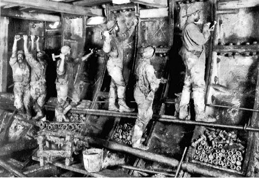
In May 1907, tunnel
workers in the south Hudson River tunnel are shown, to the right, installing
and hammering caulking material into the seams between tunnel segments. The two
men at left are tightening the bolts that held the cast-iron segments together
after installing "grummets" of red-lead-soaked yarn behind washers to
make the bolted joints watertight. Smithsonian Institution (Neg. 944987).
Completion
of the tunnels was celebrated by the engineers and tunnelers in an unusual
manner on June 21, 1909, before the track was laid. A Lozier automobile owned
by Frederic J. Gubelman, vice president of the O'Rourke firm, was lowered into
the tunnel through the Weehawken shaft and driven under the river to Tenth
Avenue in Manhattan. There a party that included Samuel Rea and Charles Jacobs
boarded the automobile for the return trip to New Jersey.
Work
proceeded on the tunnel sections on either side of the river simultaneously
with the tunneling under the Hudson. On the New York side, twin tunnels between
the Manhattan shaft and a portal at Tenth Avenue were drilled and blasted
through rock, except for several hundred feet completed by "cut and
cover" tunneling where soft material was found.
On
the New Jersey side, twin tunnels 5940 feet long were bored through the
traprock of Bergen Hill between the Weehawken shaft and the Hackensack portal.
The tunneling crews worked from both ends of each tunnel, drilling into the
hard rock with Rand "slugger" compressed air drills, then blasting
with dynamite to break up the rock. Typically, tunnel headings were first
drilled and blasted horizontally to form the upper section of the tunnel, and
then drilled and blasted vertically behind this heading on two
"bench" levels to excavate the full tunnel section. Steam shovels
loaded the excavated rock into 3-foot gauge muck trains, which were pulled out
to tunnel portals by 12-ton Vulcan steam locomotives. The hard traprock was
stored and later crushed for use as concrete aggregate and track ballast.
Drilling
through Bergen Hill proved tedious and costly. For every 10 cubic yards of rock
removed, the tunnelers used a foot of hardened drill steel and almost 30 pounds
of dynamite. Even with more than a hundred men working on each of two 10-hour
shifts, progress was limited to anywhere from 2 to 7 feet a day. The first
contract was awarded early in 1905 but the tunnels were not finished until the
end of 1908.
West
of the Hackensack portal the Meadows Division project included 5 miles of
double-track line on a high fill across the Hackensack Meadows to a junction
with the railroad's New York Division main line at Harrison; a drawbridge at a
crossing of the Hackensack River; yard and terminal facilities at Harrison,
where the change between steam and electric motive power would take place; and
a new station named Manhattan Transfer, where passengers could transfer between
trains on the PRR lines to Manhattan and Jersey City and the Hudson &
Manhattan.
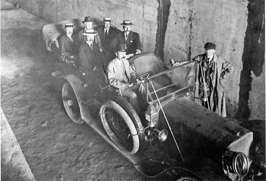
To celebrate the
completion of the tunnels, this group of Pennsylvania Railroad and contractor
officials boarded the first automobile ever driven under the Hudson River on
June 21, 1909. Seated in the rear seat, from right to left, are PRR first vice
president Samuel Rea, who was in overall charge of the project; North River
Division chief engineer Charles M. Jacobs; and Albert J. County, assistant to
the PRR's second vice president. Seated in the middle seat are tunneling
contractor John E O'Rourke, on the left, and chief assistant engineer James
Forgie. At the wheel is Frederick Gubelman, the owner of the Lozier automobile
and vice president of the O'Rourke firm. Standing at the right is George B.
Fry, O'Rourke's general tunnel superintendent. Smithsonian Institution (Neg.
84-11044).
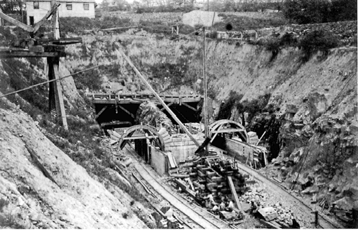
Concrete lining of the
twin tunnels under Bergen Hill was in progress when this photograph of the east
portal was taken in the Weehawken shaft on June 14, 1909. Smithsonian
Institution (Neg. 94-4979).
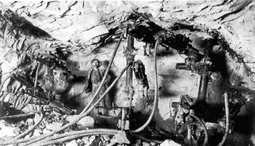
A
view of rock tunneling in the south Bergen Hill tunnel shows the compressed air
drills used to drill the holes required for blasting and the columns used to
support them. Smithsonian Institution (Neg. 944974).
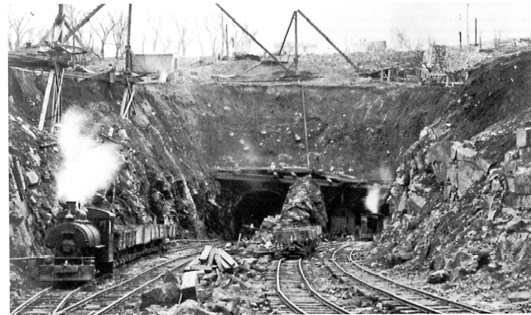
Steam engines were used
to haul Moot gauge muck trains out of the Bergen Hill tunnels. This view was
taken at the Hackensack portal on January 19, 1906. Smithsonian Institution
(Neg. 94-4973).
Another view at the
Hackensack portal, taken a year and a half later, shows the concrete tunnel
lining and masonry portal construction in progress. Smithsonian Institution
(Neg. 94-4988).
The
tunneling problems encountered by Alfred Noble, the chief engineer for the East
River section of the project, were different from those confronted by Charles
Jacobs in the Hudson River tunnels but no less difficult. The railroad planned
a four-track line east of the new Manhattan station to accommodate the movement
of Pennsylvania trains to and from Sunnyside Yard in Queens, the heavy suburban
traffic of the Long Island, and future traffic over the Hell Gate Bridge line.
just to the east of the station the tracks converged into two three-track
tunnels, one under 32nd Street and the other under 33rd Street, each narrowing
to two double-track tunnels a little farther east. Near Second Avenue the
tunnels separated into four individual tubes to cross under the East River to
Long Island City. All four tunnels descended on a 1.5-percent grade to a low
point under the East River and then rose towards the Long Island City side on a
0.7-percent grade. They passed under a Long Island Rail Road depot and yard
before coming to the surface between East and Thompson avenues. The, tracks
continued at surface level to connect with the new service and storage yard at
Sunnyside, the Long Island, and the future Hell Gate Bridge route.
Test
borings begun late in 1901 confirmed that the tunnelers would face a wide
variety of materials and conditions. Much of the tunnel route was made up of
sand, quicksand, clay, gravel, and boulders. At several locations the tunnelers
encountered layers of blue clay and very fine red sand known as bull's liver.
While the material was much firmer than the silt encountered in the Hudson
River, and was not expected to present any support problems, the engineers
expected some hard going in the wide variety of materials. For much of the
crossing, too, there would be as little as 8 feet of fine sand over the top of
the tube, insufficient to prevent a blowout of compressed air.
Because
of the expected difficulties, the engineers considered alternative methods. One
that went as far as an extended test was freezing: A small pilot tunnel would
be driven and the ground around it frozen by circulating brine at a very low
temperature through pipes in the tunnel. The pilot tunnel would then be
removed, and excavation and lining of the full tunnel section would be
completed in the frozen material. To test the idea a 7-foot 6-inch diameter
pilot tunnel was driven 160 feet under the East River and a circulating brine
system was installed. Freezing the surrounding material turned out to be a very
slow process, and the idea was given up when it was found that normal shield
tunneling was going much better than expected.
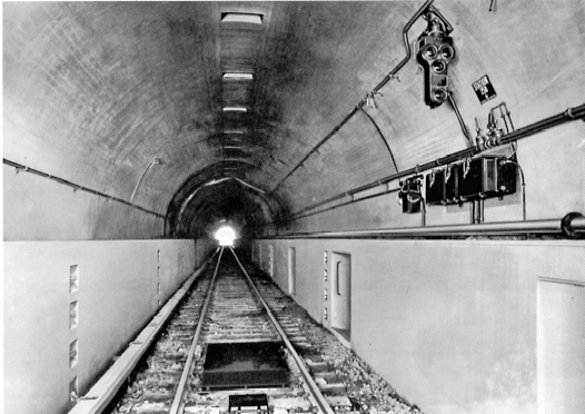
The completed tunnel
looked like this. The concrete "benches" on either side of the track
were designed to confine a train to the center of the track in case of a
derailment, and provided, at the right, a walkway for the placement of signals
and a place for signal maintainers to work safely, and, at the left, a safe
exit from the tunnel. The 675-volt DC third rail is at the left of the track.
The photograph was taken in the westbound tunnel, facing towards the Weehawken
shaft. Pennsylvania Railroad, Trains Collection.
A
contract for all four East River tubes was awarded in July 1904 to S. Pearson
& Son of London, a firm whose previous work included the Blackwall tunnel
in England and some pioneering underwater shield tunneling work on Haskin's
Hudson River tunnel during 1889 and 1890. The tunnels in the contract were
about 6000 feet long, with 3900 feet of underwater tunneling between shafts on
each side of the river and another 2000 feet below ground on the Long Island
City side.
The
four East River tubes were drilled by eight shields traveling east and west
from deep shafts sunk on either side of the river. Almost all of the tunneling
under Long Island City was completed by drilling and blasting without the use
of shields. As expected, there were frequent compressed air blowouts as the
tunnels advanced under the river. "Sudden blows were so powerful that in
one case an able-bodied man was thrown off his feet bythe rush of air,"
wrote Henry Japp, managing engineer for the Pearson firm, "and sometimes,
for brief intervals, it was impossible to make one's way out of the shield
through the doors against the in-rush of air."
"When
Tunnel B passed beyond the Manhattan ferry slip bridge," continued Japp,
"it blew out with such force that mud was thrown over the upper
cross-girder of the bridge, 40 feet above the water level, and one large niggerhead
[a colloquialism for bollard] was thrown out of the water and landed on the
bridge, breaking the decking." The loss of air from the four tubes was so
great that on one occasion, according to Japp, every machine in the compressed
air plant at Long Island City was working at full capacity, putting out at
least 456,000 cubic feet of compressed air per minute.
To
provide a greater depth of cover and control the loss of air, the contractor
dumped clay from barges to cover the line of tunnel with a blanket that
averaged 10 to 12 feet thick. This helped but did not fully solve the problem.
On June 20, 1906, before the blanket of clay had reached the desired depth,
there was a major blowout from the southernmost tunnel on the Manhattan side.
Passengers on the East River ferries heard a roar and then saw a geyser of
water rise 30 to 40 feet in the air as the compressed air rushed out. The crew
of about 20 tunnel workers ran for their lives as water flooded into the
tunnel, but two were drowned.
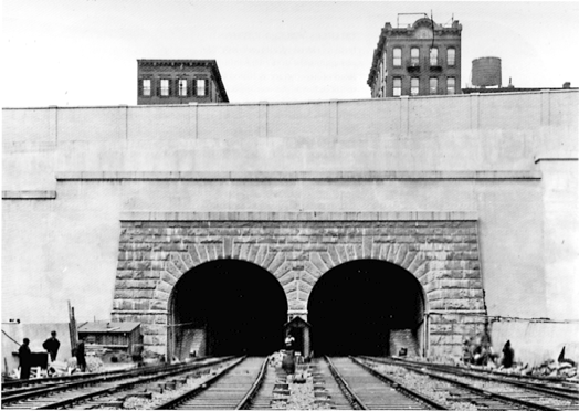
The Tenth Avenue portal
for the tunnels that brought trains into the Manhattan terminal from the west
was faced with a closegrained granite quarried at Millstone Point, Connecticut.
Museum of the City of New York.
"During
severe blows," wrote Japp, "as many as three scows, each containing
600 cubic yards of clay, have been dumped one after the other as quickly as
possible, over the blow, only to be tossed to one side by the escaping
air."
By
this time the causes and prevention of caisson disease - the bends - were well
understood. Decompression chambers and a physician at the work site were among
the precautions taken by the Pearson firm to avoid the bends among its tunnel
workers. Nonetheless, for reasons that were never fully understood, there was
an unusually high incidence of caisson disease on the project. By the end of
June 1906 there had already been 14 deaths from the bends, and a coroner's jury
had returned a verdict censuring the contractor for inadequate precautions.
The
continuing blowouts, the deaths, and a strike for higher pay and shorter hours
by the tunnel workers had the project in disarray.
"One
report had it," said The New York Times, "that there is little chance
of completing the tunnel in less than six years." The sandhogs were soon
back at work, however. The other problems were gradually solved and the
contractor was soon making good progress. On May 17, 1909, the completed
project, comprising some 23,600 feet of single track tunnel and the permanent
Manhattan and Long Island City shafts, was turned over to the railroad.
Construction
of the Manhattan crosstown tunnels between the river and the station site was
carried out from the First Avenue shaft, from two temporary shafts sunk along
32nd and 33rd streets between Fourth and Madison avenues, and from two more
shafts just west of Sixth Avenue. Except for a short section constructed in
open cut, the entire section was excavated by drilling and blasting through the
Manhattan gneiss. Steam shovels powered by compressed air and 3-foot gauge trains
powered by 10-ton electric mining locomotives were used for muck removal.
All
was now in readiness for the installation of the great system of electric
traction that had made the whole New York terminal project possible.
Return
to The Davies and Thomas Page