Casting Iron Segments
for New York Tunnels
A Tonnage Job on Which
Large Output is Demanded and the Work is Facilitated
by the Use of Jar-Ramming Molding Machines
By E C Kreutzberg
Published in The Foundry, Vol 44, Cleveland Ohio,
April 1916, P. 217
The manufacture of gray
iron castings for use in the construction of tunnels has developed in the last
decade into an exceedingly important branch of the foundry industry. During
that time several hundred thousand tons of pig iron have been converted into
tunnel castings and, owing to the remarkable manner in which these subaqueous
highways have filled the need for rapid transit facilities between New York and
the surrounding territory, it is to be expected that the demand for such
castings in the future will keep pace with the requirements of congested
centers of population where waterways are an obstruction to traffic. A
sub-aqueous tunnel driven by the shield method, although its construction calls
for engineering ability of the highest order and the working out of a
tremendous amount of detail may be described briefly as a cast iron tube,
encased in a grouting of cement, and lined with concrete. The tunnel is
constructed along a path opened by a steel shield; the latter is advanced by
hydraulic jacks and is provided with a door through which workmen pass the dirt
that they remove from in front of the shield. These men work under a hood, and
in atmosphere which is maintained under pressure to reduce to a minimum the
leakage from the riverbed above. The cast iron tube is built up of rings, which
have a length of about 2 feet along the axis of the tunnel, and a diameter
which generally varies from 17 to 20 feet, depending on the size of the tunnel.
The rings, in order that they may he handled with facility, are built up of segments,
of which there generally are 9 to 11 to a ring, depending on the diameter. The
segments are provided with holes through which the casing to cement grouting may
he applied from the interior of the tunnel, and with flanges for bolting them
together, the joints being calked. After the completion of the tube, the tunnel
is equipped with railroad tracks of piping, according to the purpose for which
it is designed.
The primary requirements
of a foundry engaging in the manufacture of tunnel castings are a large molding
floor area and a corresponding melting capacity, since the molds are of good
size and the castings are heavy and thousands of them are needed to keep
abreast of the requirements of tunnel construction. Although the methods of molding
are simple, numerous flasks and other special equipment are needed, while for
machining the segments much special machinery of unusually large size and
capacity must be installed. In fact, such work calls for specializing by the
foundry participating in it to a degree unusual in jobbing work. As a result,
only a few concerns have engaged in the manufacture of cast iron tunnel
segments. Among them is the Davies & Thomas Co., Catasauqua, Pa, one of the
first concerns to embark in the manufacture of such castings, and manufacturer
of the greater portion of the cast iron tonnage embodied in the sub-aqueous
tunnels under New York harbor. At the present time, this company has two
unfinished contracts for tunnel segments, one involving 18.000 and the other 22,000
tons, of which approximately 30,000 tons still are to be produced. The routine
worked out at this plant in the manufacture of these castings is of interest to
every foundryman.
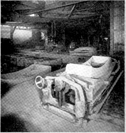
Fig. 1 Direct-Draw, Rollover, Jolt
Machine Used for Making Drags of Tunnel Segment Molds
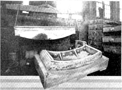
Fig. 2 Tunnel Segment Pattern and
Follow-Board and Drag Section of Flask
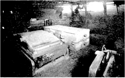
Fig. 3 Cope Molding Machine for Tunnel
Segment Castings
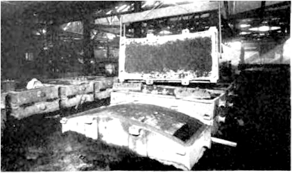
Fig. 4 Completed Cope and Drag, Showing
Type of Cores Used for Providing Bolt-Holes
Will Increase Output
At the present time the
Davies & Thomas Co. is devoting 14 molding floors to tunnel segment
castings, each floor producing 12 to 14 segments a day, resulting in a daily
output of approximately 125 tons. Plans now are being prepared to increase the
output and it is expected that by Sept. 1 the production will be about 175 tons
per day. The molding methods employed are principally of the well-known floor
type, as illustrated in Figs. 2 and 4. The pattern, shown in Fig. 2 is of
simple construction and is mounted on an ordinary wood follow-board. The flasks
are cast iron and are provided with trunnions which admit of convenient
handling by the hoists which serve each floor. The bottom of the cope is convex
and the top of the drag concave, thus providing a joint which conforms to the
contour of the pattern; the mold is located entirely in the drag, the cope
serving simply as a cover. The casting is poured through two gates, located at
one end of the flask and the mold is provided with a riser. Figs. 2 and 4
illustrate the sequence of molding operations: The drag is rammed and rolled
over, the cope is rammed and lifted, the pattern removed, the cores set in the
prints and the mold closed. These castings are made on a piecework basis, one
molder and one or two helpers to a floor, the molders engaging their helpers.
On account of the large
floor space at the company's command, and the correspondingly great output
which it thus has been able to obtain by floor molding methods, it is only within
the past few months that it has undertaken the installation of molding machines
for use in producing tunnel segment castings. The two machines in use were furnished
by the Osborn Mfg. Co., Cleveland. The one shown in Fig. 1 is a direct-draw,
roll-over jolt, used in molding the drags, while the cope machine, illustrated
in Fig. 3, is of the plain jar-ramming type. Both machines are manipulated by
compressed air. The flasks used for machine molding, as shown in Fig. 3, are
exactly file same as those used for floor molding. For removing the drags, the
roll-over machine is served by a receiving car, from which the drags may be
transferred by crane to the pouring floor. The copes, which do not include any
portion of the mold and whose function is simply to close the drags, are lifted
off the plain jolt machine by a crane which carries them to the pouring floor.
Molding sand is supplied to the machine by gravity, flowing into the flasks
from an overhead steel reservoir which has capacity for holding 45 tons. The
downtakes from the reservoir are provided with gates by which the flow of sand
may be regulated from the floor. The supply of sand in the reservoir is
replenished constantly by a bucket elevator which is fed from a pit in the
foundry floor. The molding machine installation has a capacity for turning out
a complete mold every five or six minutes; it has not yet been put in full
operation due to the fact that facilities for handling the output of the
machines have not been completed. The company is arranging for the addition of
a traveling crane and other equipment necessary for this purpose.
For each segment mold 15
dry sand cores are required to form the bolt holes in the flanges, and the tap
hole in the face of the casting. These are placed in the molds in prints which
are made by removable lugs on the pattern. The bolt hole cores are made in
large numbers, the output ranging from three to four tons a day. As shown it in
Fig. 4, they are of two sizes, the bolt holes at the end of each segment being
formed by a single large core, while each of the side bolt holes is formed by a
small core. A portion of the output of the large cores is turned out by the
usual hand method at a rate of 55 to 60 cores per day per man; the remainder of
the end cores and all of the small bolt hole cores are produced on roll-over
machines of the type manufactured by the Osborn Mfg. Co., Cleveland. Three of
these machines have been installed, one being devoted to end cores and the
remaining two to side cores. The Machine production of end cores is about 100
per day, while the side core output for each machine is approximately 1,800 per
day. The side cores are made in batches of eight. The core department is
equipped with three large coal-burning ovens and the entire floor space is
commanded by a 6-ton traveling crane.
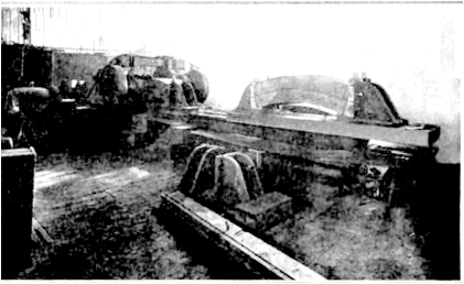
Fig. 5 Machining Sides of Segment
Castings on Larger Milling Machine
No. 2 Plain Pig Iron Used
The specifications to
which the segments must conform were drawn by the public service commission,
first district of the state of New York. These specify the use of No. 2 plain
pig iron, and for the usual physical requirements in the resulting castings.
The plant is equipped with four cupolas, three of which have capacity for
melting 12 tons an hour each, while the fourth has an output of 10 tons an
hour. At the present two 12-ton cupolas are operated and the third shortly will
be employed. The foundry is provided with a network of narrow-gage industrial
track which is utilized for distributing the metal in ladle cars. Approximately
24,000 square feet of foundry floor space is devoted to the segments.
Between the foundry and
machine shops is the cleaning department, 40 x 80 feet. A branch of the
industrial railroad which communicates with all parts of the plant extends into
the cleaning department and is equipped with three 6-ton overhead traveling
cranes. In this department the castings are cleaned superficially in order that
they may be handled with facility in the machine shop: they are subjected to a
more thorough cleaning and finishing press after they have been machined.
The castings are
delivered to the cleaning room as soon as they have been shaken-out, and after
cleaning they are coated with tar while still hot. The castings which cannot be
tarred immediately are placed in a pit in which they retain their heat until it
is convenient to coat them. The machining of tunnel segment castings is an
exacting operation, since any inaccuracies may result in serious deflections in
the work of tunnel construction. The segments now being made at the Davies
& Thomas plant are designed for assembling into rings, 18 feet in diameter
and 26 inches wide, nine segments and one key constituting a ring. Of these segments,
seven are provided with joints whose planes pass through the center of the
ring. The remaining two have one tapered joint each, thus forming an opening
into which the key segment may be inserted from the interior of the ring. The
key segments weigh about 400 pounds each, while the weight of the other
segments is approximately 1,500 pounds each. The key segments arc molded in the
same manner as the heavier segments, but the flasks are shorter and not so many
cores are required. The thickness of the metal in these castings averages 1-1/4
to l-5/8 inches. For performing the necessary machine shop operations, the Davies
& Thomas Co. has installed heavy machinery which is located in two
buildings, 55 x 160 and 55 x 110 feet, respectively. For machining the sides,
the heavier segments are placed two-high, on two 42-foot Ingersoll milling machines.
Each of these machines is driven by a 50-horsepower, direct-connected motor and
is provided with two tables, one of which may be loaded while the castings on
the other are being chucked. The machines, known as hoggers, mill both sides of
the segments simultaneously, completing two segments every 15 to 20 minutes. As
shown in Fig. 5, the segments arc held in a chuck, patented by the Davies and
Thomas Co., which was designed especially for this work.
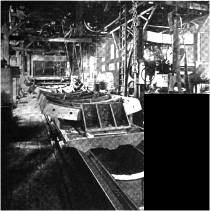
Fig 6. Machining Tapered
Ends of Segments on Large Planer with Milling Cutters
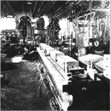
Fig. 7 Machining Key Segments on a
Milling Machine
Machining The Tapered Ends
For machining the
tapered end, the segments are placed on planers which are provided with two
milling heads each so that both ends may be machined simultaneously. Three
planers are engaged in this work, each of which has a length of 62 feet in the
shears. These planers have two tables each, thus permitting one to be loaded
while the other is under the milling cutters. A special method of driving,
involving the use of a wheel and disc friction and a worm gear, has been
applied to these planers in order that the feed of the tools may be adjusted to
keep pace with the capacity of the milling cutters as well as to permit rapid
forward and return movements when desired. Each planer table has a capacity for
holding six to eight segments and the operating time for milling the ends
averages about one hour per table. In addition, a 95-foot planer, shown in Fig.
6, like the 42-foot milling machines, is devoted to the milling of sides. This
planer also is provided with two tables, each of which has a capacity for six
segments, the machining time per table being about one hour. It is equipped
with the same special drive which has been applied to the planers engaged in
milling ends. For milling the key segments, a third Ingersoll milling machine,
shown in Fig. 7, is employed. This is equipped for milling both the ends and
sides of the key segments. For milling the ends, the table has a capacity of
seven segments, while for milling the sides, the capacity is five.
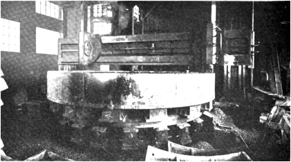
Fig. 8 Machining a 3/4 inch Taper on a
Ring which is to be Used in a Curved Section of the Tunnel
Rings which are intended
for use in curved sections of tunnels are assembled and machined on a boring
mill which has a 19-foot table, but which can take work 25 Feet in diameter.
The rings are held in a chuck which elevates one side, usually about 1/4-inch
above the level of the other, so that after the two sides have been machined,
they converge slightly, instead of being parallel to each other as in the case
of rings designed for straight sections of the tunnel. A view of the boring
mill in operation is shown in Fig, 8. Only one side of the ring is tapered on
the boring mill, the other sides of tire segments forming the ring being
machined separately on milling machines. The boring mill is served by a 6-ton
traveling crane. Each milling machine and planer is commanded by a 3-ton
traveling crane. The machine shop is equipped with two Ingersoll milling cutter
grinders which are constantly operated, due to the severe service to which the
milling cutters, both on the planers and milling machines, are subjected. In
addition to the foregoing equipment, which is used exclusively for work on
tunnel castings, the company operates a large machine shop, 50 x 150 feet,
devoted to general jobbing work.
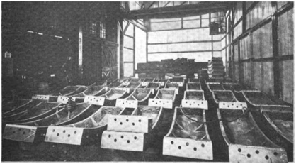
Fig. 9 Shipping Department, Where
Castings are Finished and Inspected Prior to Loading
Them on Cars
Fig. 9 shows the
finishing, inspection and shipping department, which is 30 x 150 feet and is
commanded by a 15-ton overhead traveling crane. Here all burrs and
imperfections are removed, the bolt holes are drifted to remove obstructions,
and the holes in the surfaces of the segments, which are to be used in encasing
the tunnel in a grouting of cement, are reamed and tapped, all of these
operations being performed by pneumatic tools. The inspection of the castings
is in charge of a representative of the public service commission of the first
district of the state of New York. He examines the castings for all possible
flaws, employing templates to test the accuracy of the joints and the spacing
of the bolt holes. Prior to shipping the machined surfaces of the castings are
coated with grease to prevent rusting.
Large Orders for Segments
In addition to operating
what is one of the largest jobbing foundries in the country, with a capacity
for melting 250 tons of gray iron daily, the Davies & Thomas Co. enjoys the
distinction of having supplied the major portion of the cast iron linings for
sub-aqueous tunnels driven by the shield method in this country. The contracts on
which it now is working involve l8,000 tons of
segments for the Rapid Transit railroad tunnel, which is under construction
from Old Slip, East River, Manhattan, to Clark Street to Fulton Street, Brooklyn,
and 22,000 tons for the Eastern Rapid Transit railroad tunnel from Fourteenth Street,
East River, Manhattan, to Bedford Avenue, Brooklyn. The segments on the two
contracts are identical in size and weight. On the first contract,
approximately 10,000 tons have been delivered, leaving 30,000 tons to be
produced on the two contracts. The following is a list of the tunnel segment
contracts booked by the Davies & Thomas Co. since it began the manufacture
of this kind of work in 1905:
Tons
Pennsylvania
tunnel 57,340
East
River tunnel 20,525
Hudson
& Manhattan Railroad tunnel 13,312
Steinway
tunnel 13,794
Harlem
River tunnel 2,165
East
River Gas tunnel 2,000
Roof
tunnel over the New York Central railroad tracks 838
Sewer
tunnel, Borough of Queens, Brooklyn, NY 11,000
Philadelphia
Electric In-Take tunnel 2,000
Rapid
Transit railroad tunnel 18,000
Rapid
Transit railroad, 14th street tunnel
22,000
Total
162,971
Return
to the Davies and Thomas Page
About
the Hopkin Thomas Project
January 2015